Part 1 specification, 7 address configuration – IAI America REXT User Manual
Page 60
0
Part 1 Specification
Chapter 3 Gateway R unit
40
Part 1 Specification
3.7 Address Configuration
ROBONET addresses are configured in the same manner with all four types of gateway units regardless of the type of field
network.
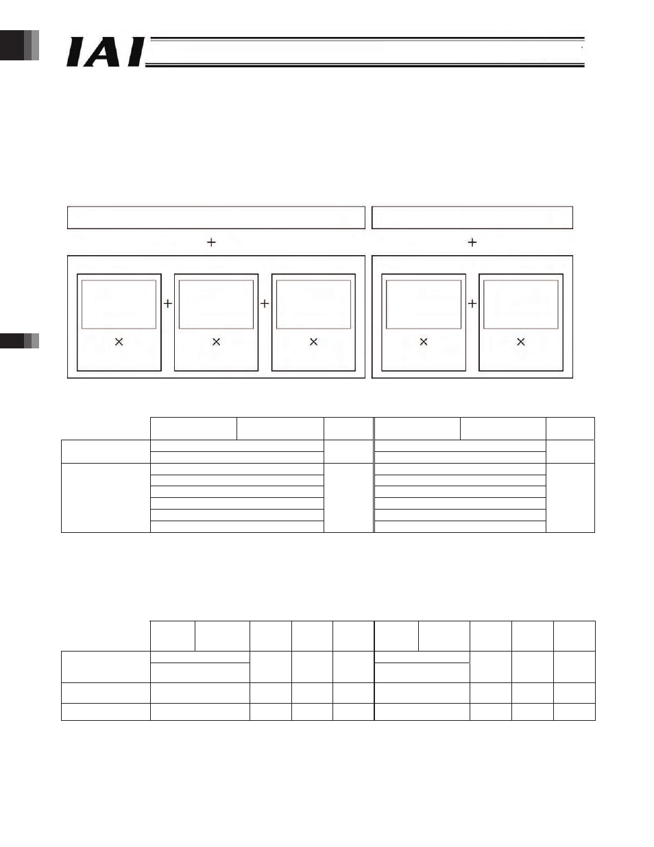
The addresses occupied by the network consist of a fixed 8-word area and a data area that changes according to the
operation mode and number of axes. The operation modes and occupied data areas are shown below.
The positioner 1 mode, simple direct mode and direct numerical specification mode can be combined, and a desired mode can
be selected for each axis. Also note that the positioner 2 mode, solenoid valve mode 1 and solenoid valve mode 2 cannot be
combined with the positioner 1 mode, simple direct mode or direct numerical specification mode.
(1) Configuration of Fixed Area
PLC output ROBONET
ROBONET PLC input
Upper byte
Lower byte
Number
of words
Upper byte
Lower byte
Number
of words
Gateway control signal 0
Gateway status signal 0
Gateway control
area
Gateway control signal 1
2
Gateway status signal 1
2
Request command
Response command
Data 0
Data 0
Data 1
Data 1
Data 2
Data 2
Data 3
Data 3
Command area
Cannot be used.
6
Cannot be used.
6
* In the direct numerical specification mode, the command area cannot be used, but this area is occupied as part of the data
area.
(2) Data Area Configuration in the Positioner Mode and Simple Direct Mode
PLC output Axis input
Axis output PLC input
Upper
byte
Lower byte
Number
of words
Positioner
mode
Simple
direct
mode
Upper
byte
Lower byte Number
of words
Positioner
mode
Simple
direct
mode
Position data specification (L)
Current position data (L)
Position data
specification area
Position data
specification (H)
2
X
{
Current position data
2
{
{
Position specification
area
Command position
number
1
{
{
Completed position
number
1
{
{
Control signal area
Control signal
1
{
{
Status signal
1
{
{
* In the positioner mode, the position data specification area (PLC Axis input) is not used, but this area is occupied as part
of the data area.
Fixed area (8 words)
Data area
Positioner 1
mode
(4 words)
Simple direct
mode
(4 words)
Direct numerical
specification
mode (8 words)
Number of axes
Number of axes
Number of axes
Fixed area (8 words)
Number of axes
Data area
Positioner 2
mode
(2 words)
Number of axes
Solenoid valve
mode 1, solenoid
valve mode 2
(2 words)
-60-