Part 1 specification – IAI America REXT User Manual
Page 114
Part 1 Specification
Chapter 3 Gateway R unit
92
Part 1 Specification
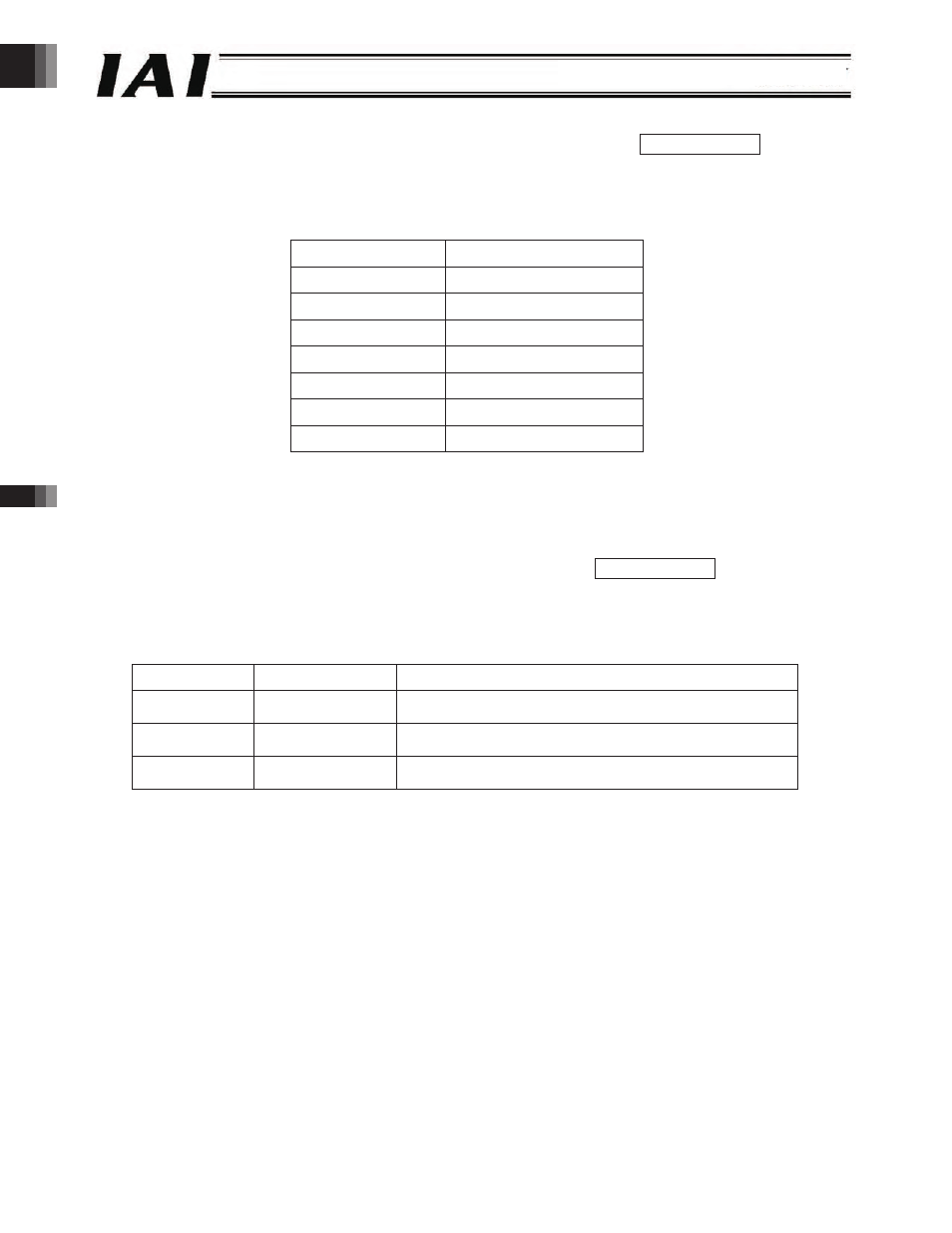
(22) Current position number signals (PE0 to PE6) [Solenoid valve mode 1] PLC input signal
When positioning is complete, a signal for the position number corresponding to the movement command (0 to 6) is
output separately.
Correspondence table of output signals and completed positions
Output signal
Completed position
PE0
Position No. 0
PE1
Position No. 1
PE2
Position No. 2
PE3
Position No. 3
PE4
Position No. 4
PE5
Position No. 5
PE6
Position No. 6
Note) These signals turn OFF when the servo turns OFF or an emergency stop is executed. If the actuator is inside the
positioning band relative to the target position when the servo turns ON again, each current position number signal
will turn ON again. If the actuator is outside the positioning band, however, the signal will remain OFF.
(23) Position detection output (LS0 to LS2) [Solenoid volume mode 2] PLC input signal
Similar to the air cylinder LS system, these signals turn ON when the current position is inside the positioning band
relative to each target position.
(Note) Even when the servo turns OFF or an emergency stop is executed while the actuator is stopped at the target position,
the applicable current position number signal will remain ON as long as the actuator is inside the positioning band.
Output signal
Position detection
Remarks
LS0
Rear end position The detection position is defined in the “Position” and
“Positioning band” fields for position No. 0.
LS1
Front end position The detection position is defined in the “Position” and
“Positioning band” fields for position No. 1.
LS2
Intermediate position The detection position is defined in the “Position” and
“Positioning band” fields for position No. 2.
-114-