Part 1 specification – IAI America REXT User Manual
Page 65
Part 1 Specification
Chapter 3 Gateway R unit
45
Part 1 Specification
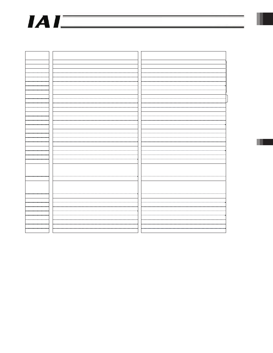
Example of Overall DeviceNet Address Configuration (positioner 2 mode and solenoid valve modes 1 and 2)
An example of connecting 16 axes in the positioner 2 mode or solenoid valve mode 1 or 2 is shown below.
PLC output ROBONET
ROBONET PLC input
Relative
channel*
Upper byte
Lower byte
Upper byte
Lower byte
0
Gateway control signal 0
Gateway status signal 0
1
Gateway control signal 1
Gateway status signal 1
2
Request command
Response command
3
Data 0
Data 0
4
Data 1
Data 1
5
Data 2
Data 2
6
Data 3
Data 3
7
(Cannot be used)
(Cannot be used)
8-word
fixed area
8
(Axis 0) Command position number
(Axis 0) Completed position number
9
(Axis 0) Control signal
(Axis 0) Status signal
10
(Axis 1) Command position number
(Axis 1) Completed position number
11
(Axis 1) Control signal
(Axis 1) Status signal
2 words
12
(Axis 2) Command position number
(Axis 2) Completed position number
13
(Axis 2) Control signal
(Axis 2) Status signal
14
(Axis 3) Command position number
(Axis 3) Completed position number
15
(Axis 3) Control signal
(Axis 3) Status signal
16
(Axis 4) Command position number
(Axis 4) Completed position number
17
(Axis 4) Control signal
(Axis 4) Status signal
18
(Axis 5) Command position number
(Axis 5) Completed position number
19
(Axis 5) Control signal
(Axis 5) Status signal
20
(Axis 6) Command position number
(Axis 6) Completed position number
21
(Axis 6) Control signal
(Axis 6) Status signal
22
(Axis 7) Command position number
(Axis 7) Completed position number
23
(Axis 7) Control signal
(Axis 7) Status signal
24
(Axis 8) Command position number
(Axis 8) Completed position number
25
(Axis 8) Control signal
(Axis 8) Status signal
26
(Axis 9) Command position number
(Axis 9) Completed position number
27
(Axis 9) Control signal
(Axis 9) Status signal
28
(Axis 10) Command position number
(Axis 10) Completed position number
29
(Axis 10) Control signal
(Axis 10) Status signal
30
(Axis 11) Command position number
(Axis 11) Completed position number
31
(Axis 11) Control signal
(Axis 11) Status signal
32
(Axis 12) Command position number
(Axis 12) Completed position number
33
(Axis 12) Control signal
(Axis 12) Status signal
34
(Axis 13) Command position number
(Axis 13) Completed position number
35
(Axis 13) Control signal
(Axis 13) Status signal
36
(Axis 14) Command position number
(Axis 14) Completed position number
37
(Axis 14) Control signal
(Axis 14) Status signal
38
(Axis 15) Command position number
(Axis 15) Completed position number
39
(Axis 15) Control signal
(Axis 15) Status signal
* The relative channel indicates the relative channel number from the first gateway channel.
-65-