Part 1 specification – IAI America REXT User Manual
Page 138
Part 1 Specification
Chapter 3 Gateway R unit
114
Part 1 Specification
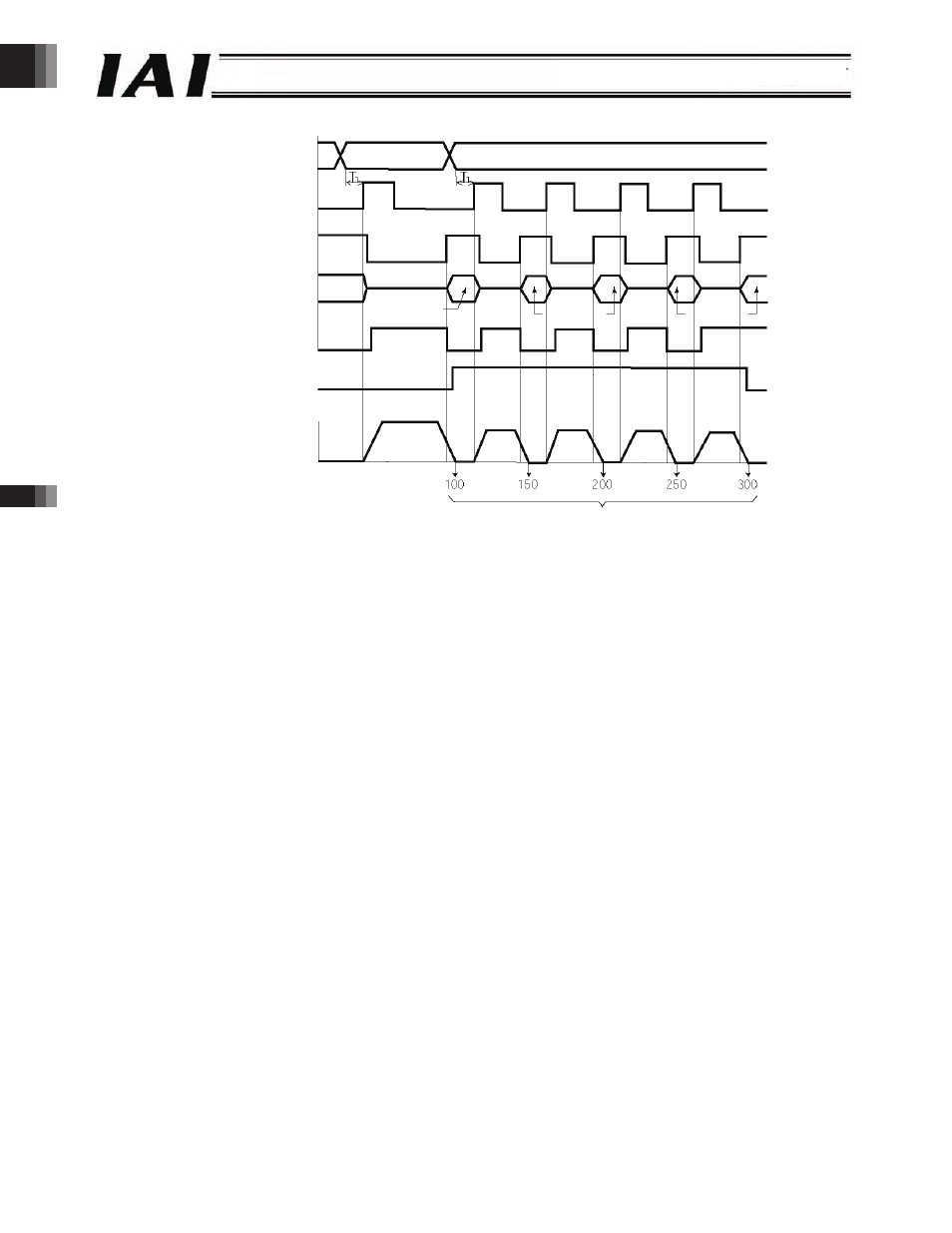
* Set an appropriate time so that “T1 t 0 ms” is satisfied, by considering the scan time of the host controller.
[Explanation of Operation]
[1] Positioning operation to position 1 (100.00 mm) is performed.
[2] Upon completion of positioning to position 1, the position complete signal (PEND) turns “1” (ON). The zone signal
(PZONE) also turns “1” (ON).
The position number is changed from 1 to 2, and the start signal (CSTR) is turned “1” (ON).
[3] Once the actuator starts moving, the position complete signal (PEND) changes from “1” (ON) to “0” (OFF) and
the moving signal (MOVE) changes from “0” (OFF) to “1” (ON). Turn the start signal (CSTR) “0” (OFF) after
confirming that the PEND has turned “0” (OFF).
[4] After the actuator has moved by 50 mm, the position complete signal (PEND) turns “1” (ON) and the moving
signal (MOVE) turns “0” (OFF) again. At this time, the PLC registers the first count in the movement counter.
Next, the start signal (CSTR) is turned “1” (ON) to start the next 50-mm movement.
[5] Steps [3] and [4] are repeated hereafter.
The PLC checks the status of the zone signal (PZONE) upon completion of positioning. If the signal is “0” (OFF), the PLC
determines that this is the last work part.
If the count in the PLC does not match the zone signal status, the signal timings may not be synchronized.
[1]
[2]
[3]
[4]
[5]
Command position
Start
(CSTR)
Position complete
(PEND)
Moving (MOVE)
Actuator movement
Completed position
Speed
Position 1
Position 2
Position 1
Position 2
Position 2
Zone signal
(PZONE)
Distances from home
Time
*
-138-