Part 1 specification, 2 led indicators – IAI America REXT User Manual
Page 46
Part 1 Specification
Chapter 3 Gateway R unit
28
Part 1 Specification
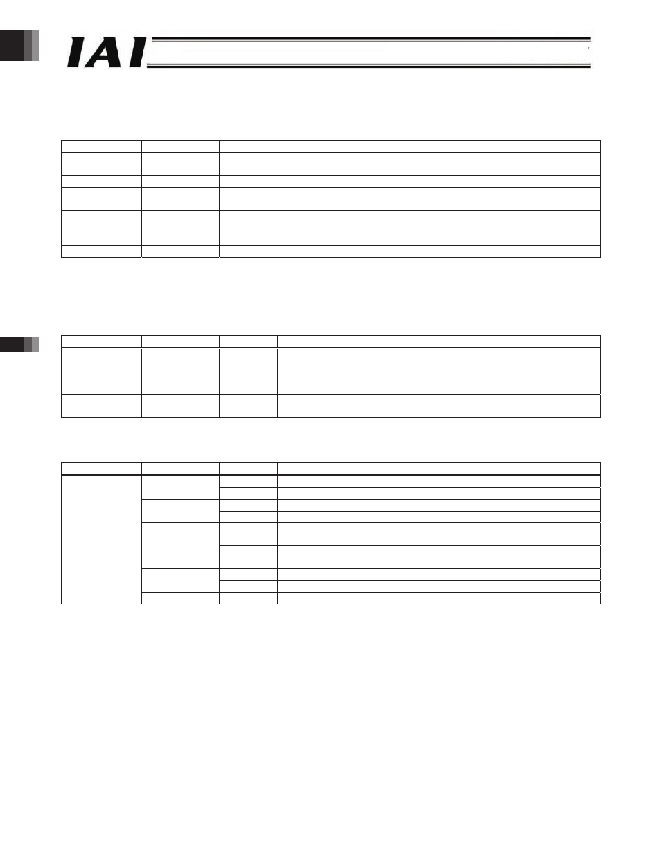
3.5.2 LED Indicators
These LEDs are used to monitor the status of the gateway unit.
Symbol
Indicator color
Explanation
RUN/ALM
Green/orange Steady green: Operating normally.
Steady orange: An error is present.
EMG
Red
This LED is lit when an emergency stop is actuated.
ERROR T
Orange
This LED is lit when a communication error is present between the controller and
internal bus.
ERROR C
Orange
This LED is lit when a communication error is present over the field network.
STATUS 1
Green/orange
STATUS 0
Green/orange
The function of this LED varies according to the field network type.
(Refer to the table below.)
AUTO
Green
This LED is lit in the AUTO (auto operation) mode.
STATUS 0 and 1 indicate the field network statuses. What these LEDs indicate vary according to the field network type, as
shown in the table below.
(1) CC-Link
Name
Indicator color
Status
Explanation
Steady
An error (CRC error, station number setting error or baud rate setting
error) is present.
STATUS 1
Orange
Blinking The station number or baud rate has changed from the set value due to a
reset.
STATUS 0
Green
Steady
A refresh & polling command has been received successfully, or a refresh
command has been received successfully, after joining the network.
(2) DiviceNet
Name
Indicator color
Status
Explanation
Steady
Online.
Green
Blinking Online (Cnx not established).
Steady
An error is present.
Orange
Blinking At least one Cnx has generated a timeout.
STATUS 1
Green/orange
Alternate Self-diagnosis is in progress.
Steady
Operating normally.
Green
Blinking No configuration information is available or the configuration information
is incomplete.
Steady
Failed (unrecoverable).
Orange
Blinking Failed (recoverable).
STATUS 0
Green/orange
Alternate Self-diagnosis is in progress.
-46-