Part specification – IAI America REXT User Manual
Page 34
Part 1 Specification
Chapter 2 System Configuration and General Specifications
Part Specification
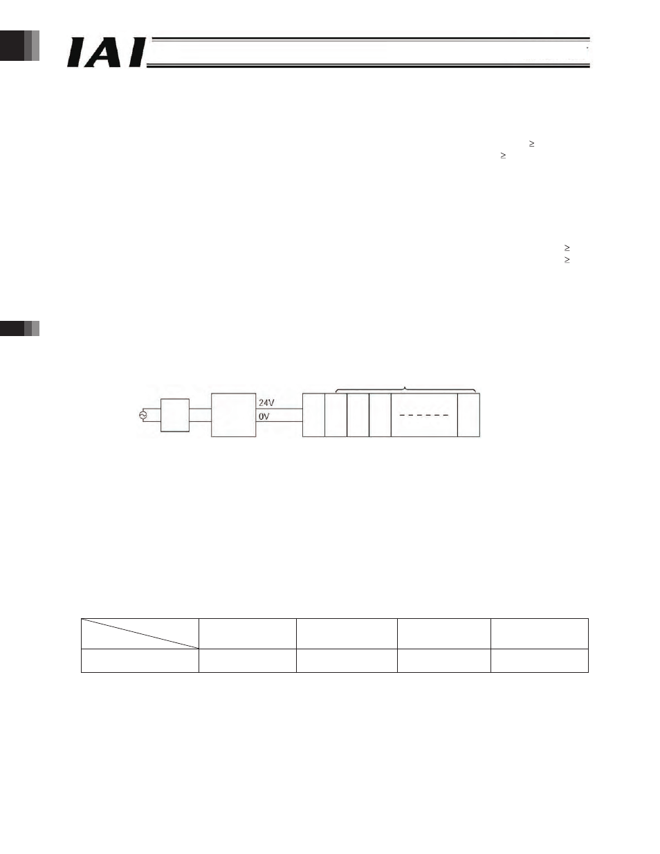
Gateway
R unit
ROBONET
RACON or RPCON (up to axes)
Circuit
breaker
Power supply
The method to select an appropriate -VDC power supply to be used with your ROBONET system is explained below.
() Current consumption of controller units when the respective axes operate simultaneously
Rated RACON current x Number of RACON controllers operating simultaneously ( ) + Rated
RPCON current x Number of RPCON controllers operating simultaneously ( )
--- []
() Current consumption of other units
= 0. A x Number of Gateway R units + 0. A x Number of simple absolute R units
]
[
-
-
-
s
ti
n
u
n
o
i
s
n
e
t
x
e
f
o
r
e
b
m
u
N
x
A
.
0
+
The current consumption is calculated by [] + [] in a steady state.
() Current consumption during excited-phase detection
Maximum RACON current x Number of RACON controllers performing excited-phase detection simultaneously ( ) +
Maximum RPCON current x Number of RPCON controllers performing excited-phase detection simultaneously ( )
--- []
Normally a power supply whose rated current is equivalent to ([] + []) x . or more is selected by considering 0 to
0% of allowance in addition to the above current consumption of [] + [].
However, make sure you select a power supply of “peak load accommodation” specification or having a sufficient
allowance because the current of [] will flow for a brief moment. In particular, exercise caution when the remote sensing
function is provided.
() It is recommended that the ROBONET power be turned on/off on the AC power supply side (primary side of
the -V power supply). If the ROBONET power is turned on/off on the output side of the -V power supply,
the large current will flow for a brief moment when the power is turned on, as explained in ().
Turning on the power on the AC power supply side causes a rush current (*) to flow where the size of this rush current is
determined by the -V power supply used. Accordingly, select a circuit breaker that will not trip when this rush current
flows.
(Example) If the PS is used as the -V power supply, a rush current of approx. 0 to 0 A will flow through the
power supply for approx. ms. (Measured value)
* The specific value varies depending on the model of the -V power supply and impedance of the power-supply line.
() The table below lists the measured ROBONET rush currents (*) that generate when the ROBONET power
is turned on/off on the DC side (secondary side of the -V power supply). (These values assume parallel
connection of three PSs as -V power supplies.)
Number of axes to axes
to axes
to axes
to axes
ROBONET rush current
Approx. 0 to 0 A,
0. ms
Approx. 00 to 0 A,
0. to 0. ms
Approx. to 0 A,
0. to 0. ms
Approx. 0 A
.0 to . ms
* The specific ROBONET rush current varies depending on the model of the -V power supply and impedance of the
power-supply line. The values in the above table
* If turning the power on/off is necessary on -V side, keep the 0-V connected and connect/disconnect the -V line.
are reference values only and not guaranteed.
-34-