Part 1 specification – IAI America REXT User Manual
Page 172
0
Part 1 Specification
Chapter 3 Gateway R unit
148
Part 1 Specification
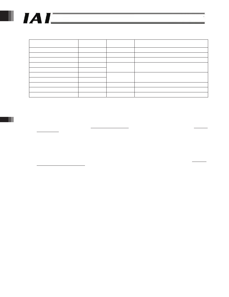
Jog+ Command (JOG+)
z
Query
Field name
RTU mode data
(8 bits)
Data length
(bytes)
Remarks
Header
None
-
Slave address
3F H
1
Fixed.
Function code
06 H
1
Starting address
(upper)
F6 H
Starting address
(lower)
0B H
2
Address of the control signal register of axis (0)
New data (data written) (upper)
Arbitrary
New data (data written) (lower)
Arbitrary
2
Used in combination with the JISL and JVEL
signals.
Error check
(CRC)
16 bits
2
Based on calculation result
Trailer
None
-
Total bytes
8
z
Response
If the data has been changed (written) successfully, the response is the same as the query.
[Function] This signal is used to start jogging operation or inching operation.
Jogging Operation in + Direction
When the JOG+ signal is turned “1” while the JISL signal is “0” (jogging mode), the actuator will jog in the direction
opposite home. The speed corresponds to the jogging speed of the parameter specified by the JVEL signal, while
the acceleration/deceleration corresponds to the rated acceleration/deceleration (the specific value varies
depending on the actuator).
How to Stop Jogging Operation in + Direction
x
Change the JOG+ signal from “1” to “0” during operation.
x
Change the JOG- signal from “0” to “1” during operation.
Inching Operation
The actuator will inch in the direction opposite home every time the JOG+ signal changes from “0” to “1” while the
JISL signal is “1” (inching mode). The speed and travel distance correspond to the jogging speed and inching
distance of the parameters specified by the JVEL signal, while the acceleration/deceleration corresponds to the
rated acceleration/deceleration (the specific value varies depending on the actuator).
-172-