Part 1 specification, Caution, Recommended emergency stop circuit – IAI America REXT User Manual
Page 50
Part 1 Specification
Chapter 3 Gateway R unit
32
Part 1 Specification
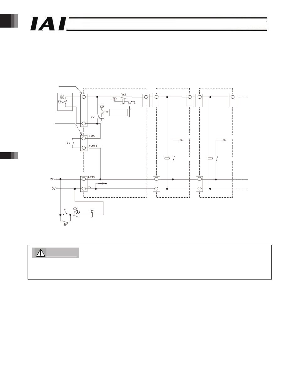
Recommended Emergency Stop Circuit
Shown below is an example of an emergency stop circuit of a ROBONET system.
The built-in drive-source cutoff relays of all axis controller units are turned ON/OFF simultaneously using the emergency stop
switch of the emergency stop circuit or teaching pendant connected to the Gateway R unit.
Caution
If an emergency stop is actuated with the emergency stop button, the emergency stop can be reset using the emergency
stop reset switch. If an emergency stop is actuated with a teaching pendant, however, the emergency switch will be reset
when the same emergency switch is turned and reset.
EMG connector
TP connector
Teaching pendant
Gateway R unit
Axis controller unit
Axis controller unit
ROBONET Communication Connector
TP connection
detection circuit
Drive-source cutoff signal
(CPU control signal)
Motor drive source
Motor drive source
Drive-source cutoff relay
Drive-source cutoff relay
Power-supply input terminal block
Internal power supply
common GND
Emergency
stop reset Emergency stop
-50-