Part 1 specification – IAI America REXT User Manual
Page 62
Part 1 Specification
Chapter 3 Gateway R unit
42
Part 1 Specification
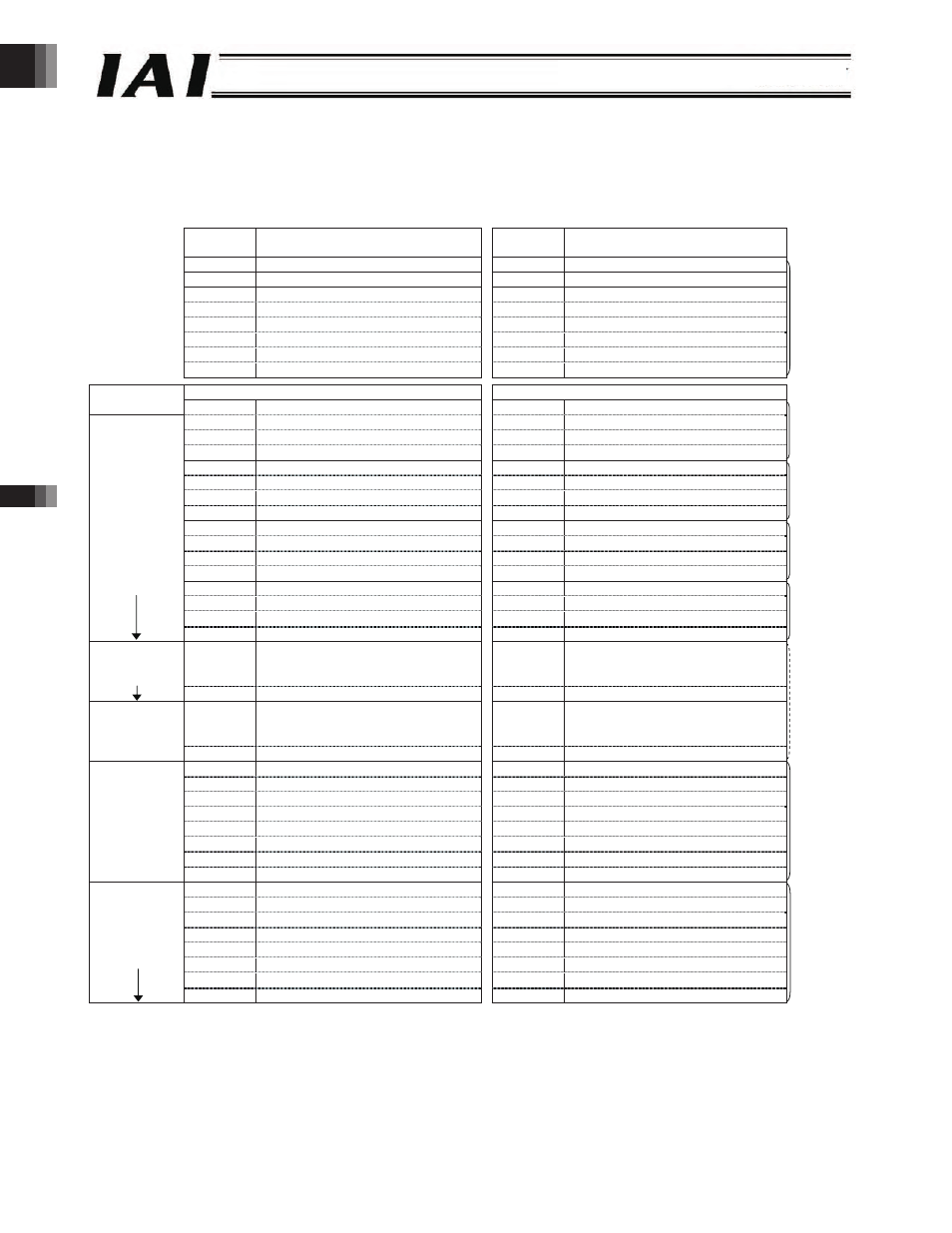
Example of Overall CC-Link Address Configuration
(Positioner 1 mode/simple direct mode + Direct numerical specification mode)
An example of connecting 12 axes operating in the positioner 1 mode or simple direct mode and two axes operating in the
direct numerical specification mode is shown.
PLC output ROBONET
ROBONET PLC input
Output
register
Upper byte
Lower byte
Input
register
Upper byte
Lower byte
RY0F to 00
Gateway control signal 0
RX0F to 00
Gateway status signal 0
RY1F to 10
Gateway control signal 1
RX1F to 10
Gateway status signal 1
RY2F to 20
Request command
RX2F to 20
Response command
RY3F to 30
Data 0
RX3F to 30
Data 0
RY4F to 40
Data 1
RX4F to 40
Data 1
RY5F to 50
Data 2
RX5F to 50
Data 2
RY6F to 60
Data 3
RX6F to 60
Data 3
RY7F to 70
(Cannot be used)
RX7F to 70
(Cannot be used)
8-word
fixed area
*1
Output register
Input register
PLC master expanded
cyclic setting
R
Ww 00H (Axis 0) Position data specification (L)
R
Wr 00H
(Axis 0) Current position data (L)
R
Ww 01H (Axis 0) Position data specification (H)
R
Wr 01H
(Axis 0) Current position data (H)
R
Ww 02H
(Axis 0) Command position number
R
Wr 02H
(Axis 0) Completed position number
R
Ww 03H
(Axis 0) Control signal
R
Wr 03H
(Axis 0) Status signal
4 words
Positioner/
simple direct
mode
R
Ww 04H (Axis 1) Position data specification (L)
R
Wr 04H
(Axis 1) Current position data (L)
R
Ww 05H (Axis 1) Position data specification (H)
R
Wr 05H
(Axis 1) Current position data (H)
R
Ww 06H
(Axis 1) Command position number
R
Wr 06H
(Axis 1) Completed position number
R
Ww 07H
(Axis 1) Control signal
R
Wr 07H
(Axis 1) Status signal
4 words
R
Ww 08H (Axis 2) Position data specification (L)
R
Wr 08H
(Axis 2) Current position data (L)
R
Ww 09H (Axis 2) Position data specification (H)
R
Wr 09H
(Axis 2) Current position data (H)
R
Ww 0AH
(Axis 2) Command position number
R
Wr 0AH
(Axis 2) Completed position number
R
Ww 0BH
(Axis 2) Control signal
R
Wr 0BH
(Axis 2) Status signal
4 words
R
Ww 0CH (Axis 3) Position data specification (L)
R
Wr 0CH
(Axis 3) Current position data (L)
R
Ww 0DH (Axis 3) Position data specification (H)
R
Wr 0DH
(Axis 3) Current position data (H)
R
Ww 0EH
(Axis 3) Command position number
R
Wr 0EH
(Axis 3) Completed position number
16 words
x1 setting,
4 stations
*2
R
Ww 0FH
(Axis 3) Control signal
R
Wr 0FH
(Axis 3) Status signal
4 words
32 words
x4 setting,
2 stations
R
Ww 1FH
(Axis 7) Control signal
R
Wr 1FH
(Axis 7) Status signal
R
Ww 2FH
(Axis 11) Control signal
R
Wr 2FH
(Axis 11) Status signal
4 words
RWw 30H (Axis 12) Position data specification (L)
R
Wr 30H
(Axis 12) Current position data (L)
RWw 31H (Axis 12) Position data specification (H)
R
Wr 31H
(Axis 12) Current position data (H)
RWw 32H
(Axis 12) Positioning band specification (L)
R
Wr 32H
(Axis 12) Current electrical current (L)
RWw 33H
(Axis 12) Positioning band specification (H)
R
Wr 33H
(Axis 12) Current electrical current (H)
RWw 34H
(Axis 12) Speed specification
R
Wr 34H
(Axis 12) Current speed data
RWw 35H
(Axis 12) Acceleration/deceleration specification
R
Wr 35H
(Cannot be used)
RWw 36H
(Axis 12) Push-current limiting value
R
Wr 36H
(Axis 12) Alarm code
RWw 37H
(Axis12) Control signal
R
Wr 37H
(Axis 12) Status signal
8 words
Direct
numerical
specification
mode
RWw 38H (Axis 13) Position data specification (L)
R
Wr 38H
(Axis 13) Current position data (L)
RWw 39H (Axis 13) Position data specification (H)
R
Wr 39H
(Axis 13) Current position data (H)
RWw 3AH
(Axis 13) Positioning band specification (L)
R
Wr 3AH
(Axis 13) Current electrical current (L)
RWw 3BH
(Axis 13) Positioning band specification (H)
R
Wr 3BH
(Axis 13) Current electrical current (H)
RWw 3CH
(Axis 13) Speed specification
R
Wr 3CH
(Axis 13) Current speed data
RWw 3DH
(Axis 13) Acceleration/deceleration specification
R
Wr 3DH
(Cannot be used)
RWw 3EH
(Axis 13) Push-current limiting value
R
Wr 3EH
(Axis 13) Alarm code
64 words
x8 setting,
2 stations
RWw 3FH
(Axis13) Control signal
R
Wr 3FH
(Axis 13) Status signal
8 words
*1 The extended cyclic setting is based on the occupied area information displayed using the gateway parameter setting tool.
*2 CC-Link Version 1.10 is also supplied as long as the expanded cyclic setting of x1 (four stations occupied) can be used.
-62-