Part 2 startup chapter – IAI America REXT User Manual
Page 286
Part 2 Startup Chapter
Chapter 2 Mounting and Installation
262
Part 2 Startup Chapter
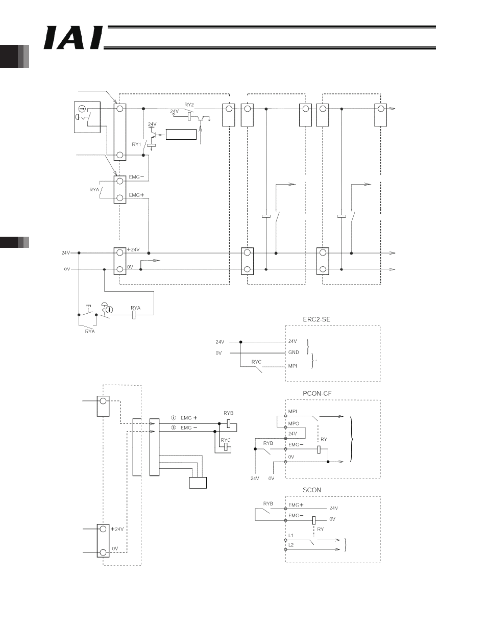
(2) An emergency stop circuit for normal layout when external SIO link is used is shown below.
[1]
[3]
[1]
[2]
[3]
EMG connector
TP connector
Teaching pendant
Gateway R unit
Axis controller unit
ROBONET Communication Connector
Drive-source cutoff signal
(CPU control signal)
Motor drive source
Drive-source cutoff relay
Power-supply input terminal block
Internal power supply common
GND
Emergency
stop reset Emergency stop
TP connection
detection circuit
Axis controller unit
Motor drive source
Drive-source cutoff relay
red
black
yellow
(orange)
(gray)
Controller connection
cable
Control power
e-CON connector
Motor drive power
Motor
Motor
[2]
Extension unit
-286-