Part 1 specification – IAI America REXT User Manual
Page 113
Part 1 Specification
Chapter 3 Gateway R unit
91
Part 1 Specification
(20) Start position commands (ST0 to ST6) [Solenoid valve mode 1] PLC output signal
Upon detection of the OFF Æ ON leading edge of any of these signals or an ON level signal for such signal, the actuator
starts positioning to the target position specified by corresponding position data.
Before issuing a start position command, the target position, speed and other operation data must be set in the position
table using a PC or teaching pendant.
Also note that if an ON signal is detected for two or more start position commands at the same time, the detected
position command of the youngest number will be executed. (Example: If an ON signal is detected for ST0 and ST1 at
the same time, the actuator will start moving to ST0.)
Although each command is executed based on detection of an ON signal for the applicable signal, priority is given to the
command whose ON signal is detected first, meaning that a signal input while the actuator is moving will not affect the
current actuator operation. Even if the signal for a different position is turned ON while the actuator is moving, the
actuator will not start moving to the applicable position after reaching the target position.
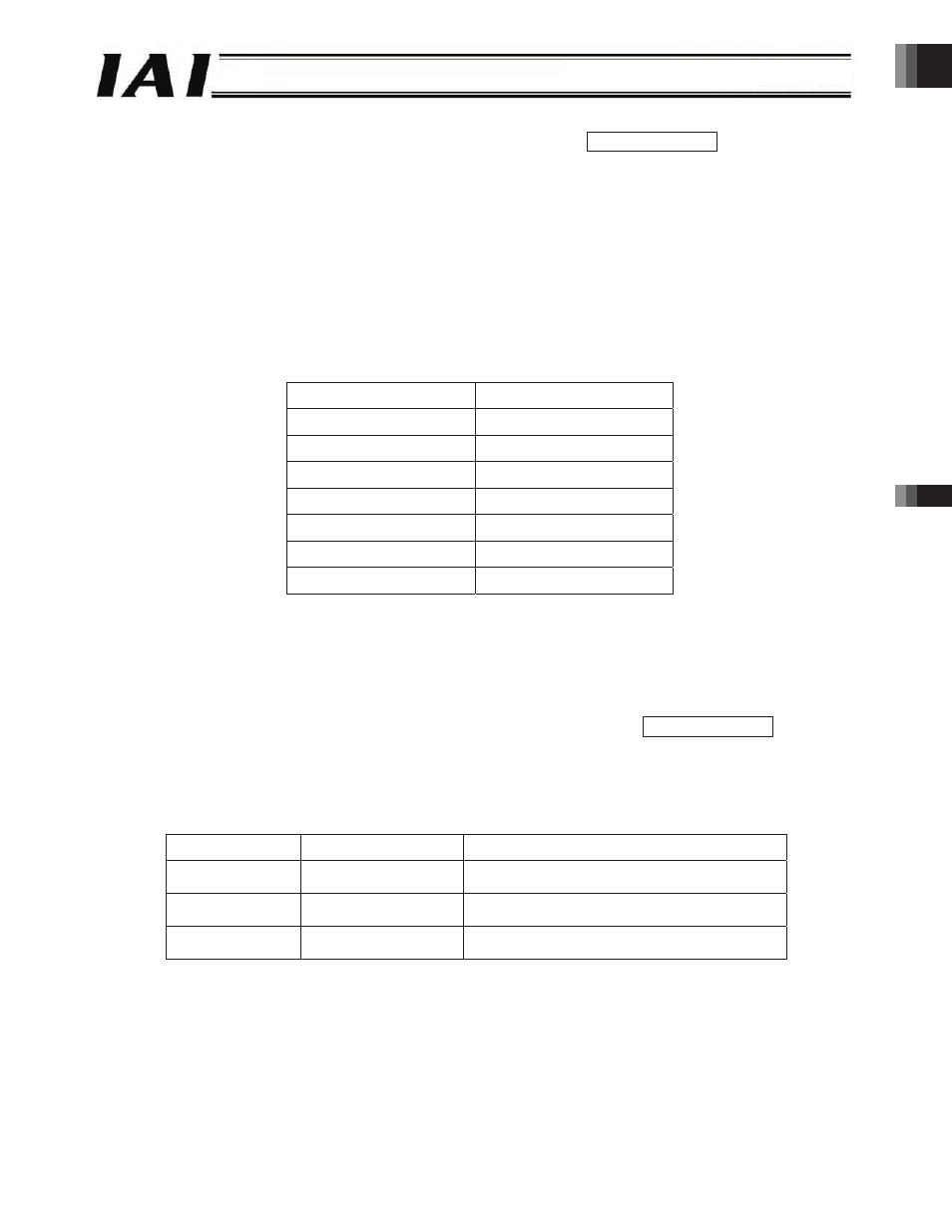
Correspondence table of input signals and command positions
Input signal
Command position
ST0
Position No. 0
ST1
Position No. 1
ST2
Position No. 2
ST3
Position No. 3
ST4
Position No. 4
ST5
Position No. 5
ST6
Position No. 6
If any of these commands is issued when the actuator has not yet completed a single home return operation following
the power on, the actuator will automatically perform a home return operation and then move to the target position.
(21) Front end movement command (ST1)
Rear end movement command (ST0)
Intermediate point movement command (ST2) [Solenoid valve mode 2] PLC output signal
While any of these signals is ON, the actuator continues to move to the applicable target position.
If the signal turns OFF during movement, the actuator will decelerate to a stop.
Before executing any of these commands, enter the target position in the “Position” field of the position table for position
No. 0, 1 or 2.
Input signal
Target position
Command position
ST0
Rear end
The target position is defined in the “Position”
field for position No. 0.
ST1
Front end
The target position is defined in the “Position”
field for position No. 1.
ST2
Intermediate point
The target position is defined in the “Position”
field for position No. 2.
-113-