Part 2 startup chapter, 5 multi-stage robonet layout – IAI America REXT User Manual
Page 280
Part 2 Startup Chapter
Chapter 2 Mounting and Installation
256
Part 2 Startup Chapter
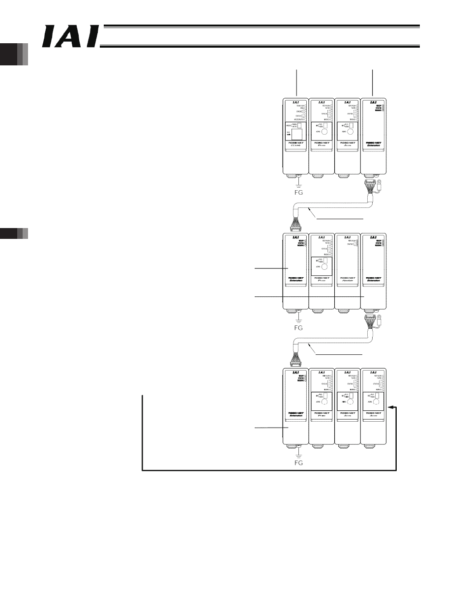
2.2.5 Multi-stage ROBONET Layout
An example of a multi-stage layout
achieved by using REXT extension units
is shown to the right.
(1) The units are installed on DIN rails.
(2) Each extension unit connected to
the downstream side (stage below)
is placed at the far right in each
stage. (Extension units [1] and [3])
(3) Each extension unit connected to
the upstream side (stage above) is
placed at the far left in each stage.
(Extension units [2] and [4])
(4) The extension units on the
upstream side (in the stage above)
and downstream side (in the stage
below) are connected using a unit
link cable (CB-REXT-SIO-), and the
grounding wire with a M3 round
terminal is connected to the FG
terminal block on each upstream
extension unit. (Extension units [1]
and [3])
Connect the FG terminals on the
downstream extension units ([2],
[4]) to the grounding terminal on the
control panel in the same manner
as with the Gateway R unit.
(5) Connect each extension unit to an
adjacent unit using the power
supply connection plate and
communication connection circuit
board supplied with the extension
unit.
(6) Install the terminal resistor circuit
board (supplied with the Gateway R
unit) on the last controller unit.
Unit link cable
GatewayR unit
Extension unit [1]
Extension unit [2]
Extension unit [4]
Unit link cable
Extension unit [3]
-280-