Part 1 specification – IAI America REXT User Manual
Page 229
0
Part 1 Specification
Chapter 4 Controller Unit
205
Part 1 Specification
z
Speed Override (No. 46, OVRD)
This parameter is used if you want to move the actuator at a slower speed to prevent danger during trial operation or at
startup.
When issuing a move command from the PLC, you can override the travel speed set in the “Speed” field of the position table
by multiplying it with the value set in parameter No. 46.
Actual travel speed = [Speed set in the position table] x [Value of parameter No. 46] / 100
Example) Value in the “Speed” field of the position table: 500 (mm/s)
Value of parameter No. 46: 20 (%)
In this case, the actual travel speed becomes 100 mm/s.
The minimum setting unit is 1%, and the input range is 1 to 100 (%). The factory setting is “100” (%).
This parameter is not effective on the move commands issued from a PC or teaching pendant, or the move commands by
direct numerical specification.
If a PC or teaching pendant is used, you can set a speed ratio in each tool to operate the actuator accordingly.
z
Default Direction of Excited Phase Signal Detection (No. 28, PDIR1)
The excited phase is detected when the servo is turned ON for the first time after turning on the power. This parameter defines
the direction of this detection.
This parameter need not be changed in normal conditions of use. However, if the actuator is contacting a mechanical end or
any obstacle when the power is turned on and cannot be moved by hand, change the direction of detection to one in which the
motor can be driven easily.
To do this, set the value of parameter No. 28 to either “0” or “1.” If the direction of detection is to be the same as the home
return direction, specify the same value currently set in parameter No. 5, “Home return direction.”
To set the direction opposite home return direction, specify the value different from the one currently set in parameter No. 5,
“Home return direction.”
This parameter is effective only when the pole sensing type is set to the current suppression mode.
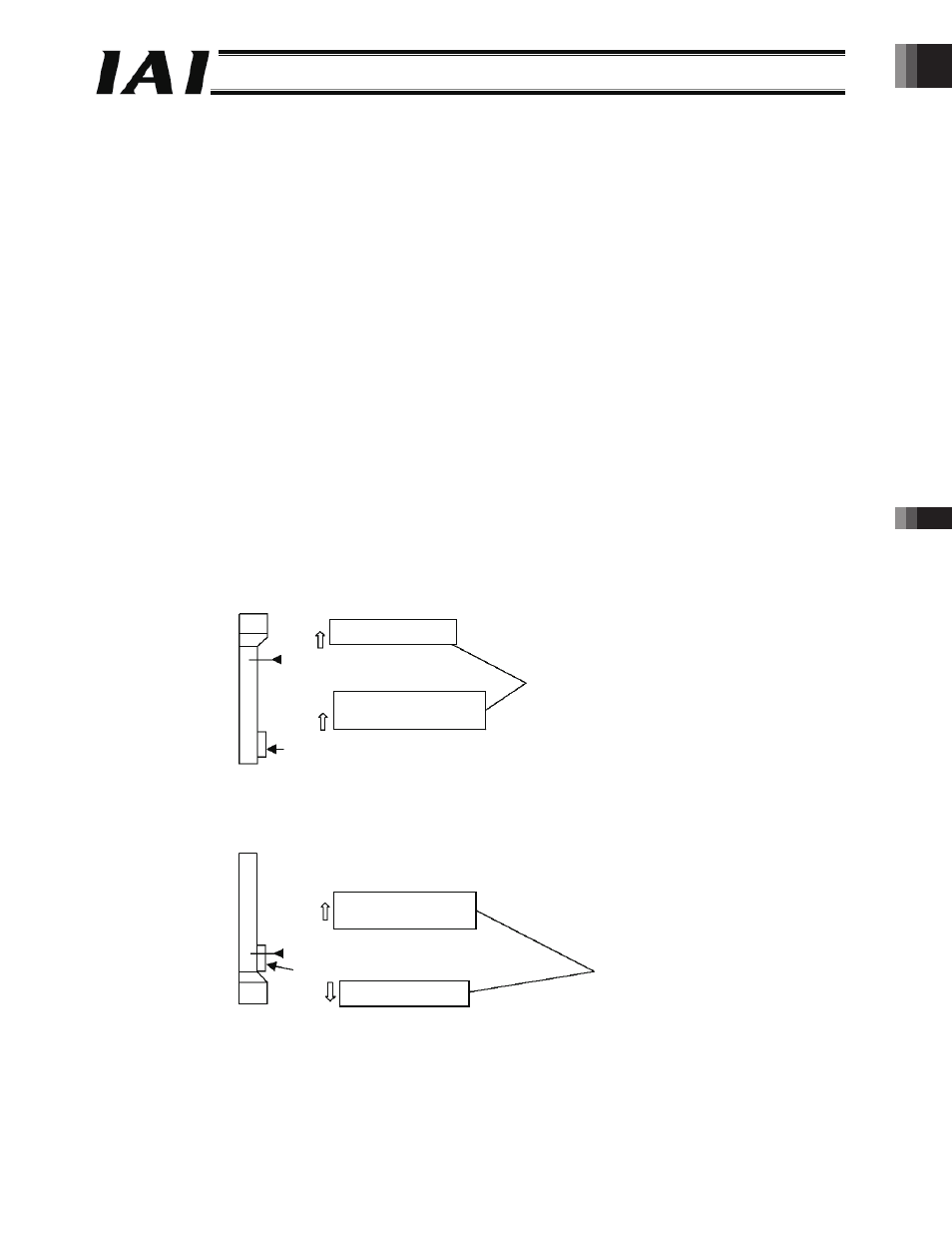
(Example 1) The power is turned on when the slider is contacting the bottom mechanical end in a vertical configuration where
the motor is positioned at the top.
(Example 2) The power is turned on when the slider is contacting the bottom mechanical end in a vertical configuration where
the motor is positioned at the bottom.
Top
Bottom
Home position
Home return direction
Direction of excited phase
signal detection
Set to the same value.
The slider is contacting the bottom mechanical end.
Top
Bottom
Home position
Direction of excited
phase signal detection
Home return direction
Set to reverse values.
The slider is contacting the bottom mechanical end.
-229-