Part 2 startup chapter, Caution – IAI America REXT User Manual
Page 281
Part 2 Startup Chapter
Chapter 2 Mounting and Installation
257
Part 2 Startup Chapter
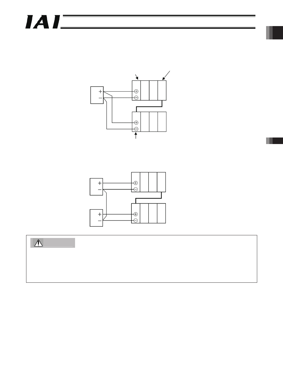
24-V power supply
GatewayR unit
Extension unit
Extension unit
24-V power supply
24-V power supply
(7) Connect the power supply (+24 V, 0 V) to the unit positioned at the far left in each stage using a
twisted pair cable. The power rise timing should be the same for all stages.
[1] Example of supplying power from one power supply
[2] Example of supplying power from multiple power supplies
Caution
1. Use a common 0-V line for the power supply connected to each stage.
2. Be sure to install the RABU unit (simple absolute R unit) paired with each RPCON unit or RACON unit in the same row
(stage) as the applicable controller unit.
3. Keep the total distance of internal SIO communication lines of the ROBONET system (distance from the Gateway R unit
to the terminal resistor of the last controller) to 30 m or less.
-281-