Part 2 startup chapter, 8 network wiring – IAI America REXT User Manual
Page 288
Part 2 Startup Chapter
Chapter 2 Mounting and Installation
264
Part 2 Startup Chapter
2.2.8 Network Wiring
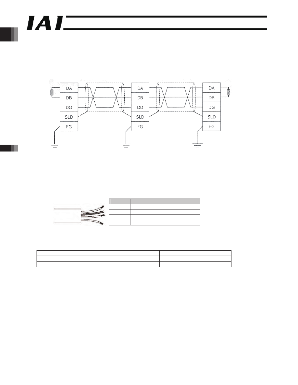
(1) CC-Link
Check the operation manual for the master (PLC) for details on CC-Link. The following explains the points to note
regarding network wiring.
An example of network connection is shown below.
[1]
An equipment connected via CC-Link is called a “station,” and 1 to 64 can be set as slave station numbers. Both
master and slave stations can be set in any positions.
[2]
Each station is connected based on direct line branching at the station. T-branches using commercial terminal
blocks, etc., are also supported.
[3]
Use a dedicated 3-core shielded twisted pair cable for CC-Link.
The details of the dedicated cable are as follows.
Color
Signal type
Blue
Communication line A (DA)
White Communication line B (DB)
Yellow Communication ground line (DG)
---
Shield (SLD)
[4]
A terminal resistor must be installed on both ends of the CC-Link system. Each terminal resistor is connected
between “DA” and “DB.” Take note that the required terminal resistor varies depending on the applicable cable,
as shown below.
Cable name
Terminal resistor
Dedicated CC-Link cable (ver. 1.00, ver. 1.10)
110 :, 1/2 W
Dedicated high-performance CC-Link cable (ver. 1.00)
130 :, 1/2 W
[5]
The baud rate is limited by the length of the network (total branch line length, maximum network length).
Terminal
resistor
Master station
Slave station
Slave station
Terminal
resistor
Dedicated CC-Link cable
(Blue)
(White)
(Yellow)
Dedicated CC-Link cable
-288-