Part 1 specification – IAI America REXT User Manual
Page 63
Part 1 Specification
Chapter 3 Gateway R unit
43
Part 1 Specification
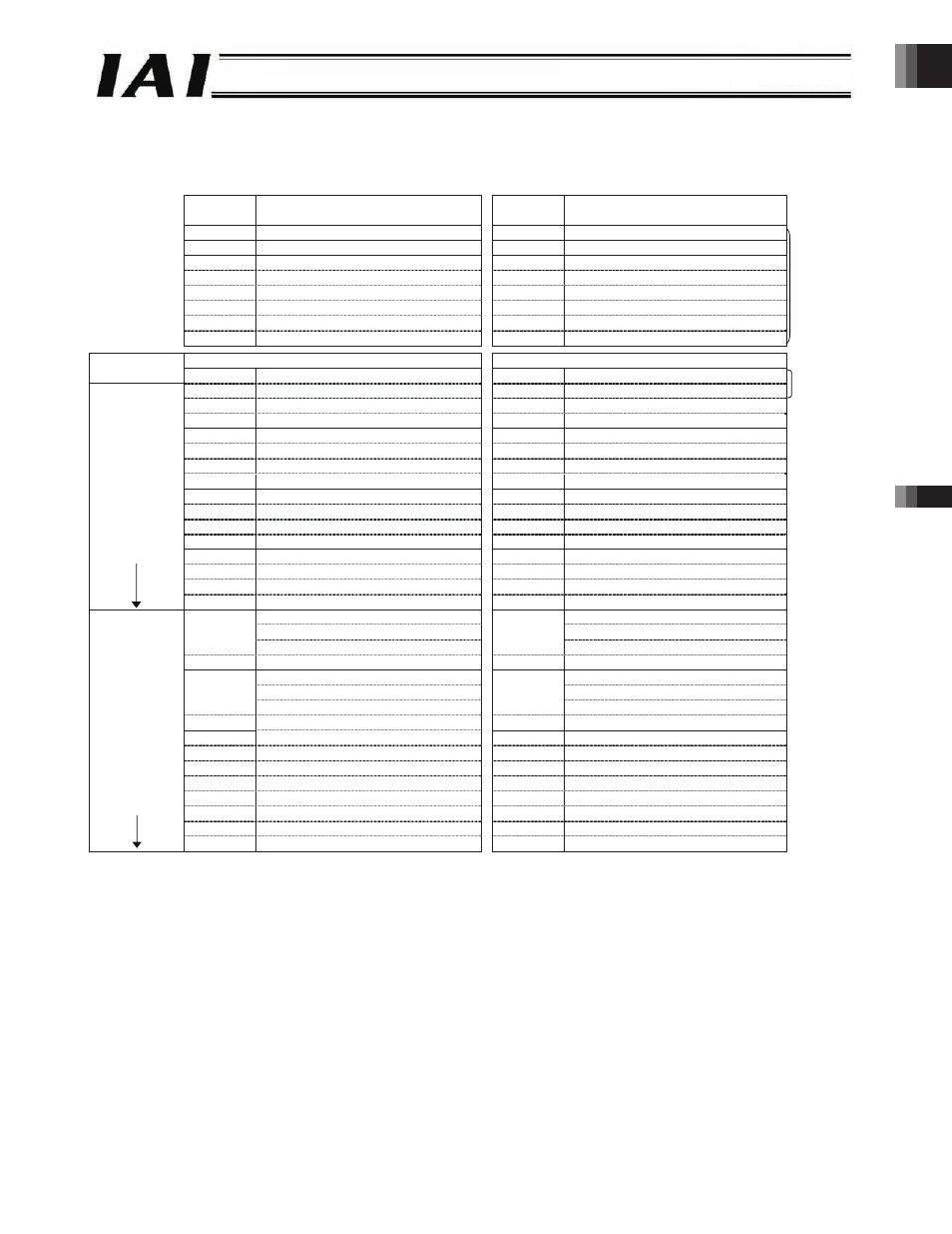
Example of Overall CC-Link Address Configuration (positioner 2 mode and solenoid valve modes 1 and 2)
An example of connecting 16 axes in the positioner 2 mode or solenoid valve mode 1 or 2 is shown below.
PLC output ROBONET
ROBONET PLC input
Output
register
Upper byte
Lower byte
Input
register
Upper byte
Lower byte
RY0F to 00
Gateway control signal 0
RX0F to 00
Gateway status signal 0
RY1F to 10
Gateway control signal 1
RX1F to 10
Gateway status signal 1
RY2F to 20
Request command
RX2F to 20
Response command
RY3F to 30
Data 0
RX3F to 30
Data 0
RY4F to 40
Data 1
RX4F to 40
Data 1
RY5F to 50
Data 2
RX5F to 50
Data 2
RY6F to 60
Data 3
RX6F to 60
Data 3
RY7F to 70
(Cannot be used)
RX7F to 70
(Cannot be used)
8-word
fixed area
*1
Output register
Input register
PLC master expanded
cyclic setting
R
Ww 00H
(Axis 0) Command position number
R
Wr 00H
(Axis 0) Completed position number
R
Ww 01H
(Axis 0) Control signal
R
Wr 01H
(Axis 0) Status signal
R
Ww 02H
(Axis 1) Command position number
R
Wr 02H
(Axis 1) Completed position number
R
Ww 03H
(Axis 1) Control signal
R
Wr 03H
(Axis 1) Status signal
2 words
R
Ww 04H
(Axis 2) Command position number
R
Wr 04H
(Axis 2) Completed position number
R
Ww 05H
(Axis 2) Control signal
R
Wr 05H
(Axis 2) Status signal
R
Ww 06H
(Axis 3) Command position number
R
Wr 06H
(Axis 3) Completed position number
R
Ww 07H
(Axis 3) Control signal
R
Wr 07H
(Axis 3) Status signal
R
Ww 08H
(Axis 4) Command position number
R
Wr 08H
(Axis 4) Completed position number
R
Ww 09H
(Axis 4) Control signal
R
Wr 09H
(Axis 4) Status signal
R
Ww 0AH
(Axis 5) Command position number
R
Wr 0AH
(Axis 5) Completed position number
R
Ww 0BH
(Axis 5) Control signal
R
Wr 0BH
(Axis 5) Status signal
R
Ww 0CH
(Axis 6) Command position number
R
Wr 0CH
(Axis 6) Completed position number
R
Ww 0DH
(Axis 6) Control signal
R
Wr 0DH
(Axis 6) Status signal
R
Ww 0EH
(Axis 7) Command position number
R
Wr 0EH
(Axis 7) Completed position number
16 words
x1 setting,
4 stations
*2
R
Ww 0FH
(Axis 7) Control signal
R
Wr 0FH
(Axis 7) Status signal
RWw 10H
(Axis 8) Command position number
R
Wr 10H
(Axis 8) Completed position number
RWw 11H
(Axis 8) Control signal
R
Wr 11H
(Axis 8) Status signal
RWw 12H
(Axis 9) Command position number
R
Wr 12H
(Axis 9) Completed position number
RWw 13H
(Axis 9) Control signal
R
Wr 13H
(Axis 9) Status signal
RWw 14H
(Axis 10) Command position number
R
Wr 14H
(Axis 10) Completed position number
RWw 15H
(Axis 10) Control signal
R
Wr 15H
(Axis 10) Status signal
RWw 16H
(Axis 11) Command position number
R
Wr 16H
(Axis 11) Completed position number
RWw 17H
(Axis 11) Control signal
R
Wr 17H
(Axis 11) Status signal
RWw 18H
(Axis 12) Command position number
R
Wr 18H
(Axis 12) Completed position number
RWw 19H
(Axis 12) Control signal
R
Wr 19H
(Axis 12) Status signal
RWw 1AH
(Axis 13) Command position number
R
Wr 1AH
(Axis 13) Completed position number
RWw 1BH
(Axis 13) Control signal
R
Wr 1BH
(Axis 13) Status signal
RWw 1CH
(Axis 14) Command position number
R
Wr 1CH
(Axis 14) Completed position number
RWw 1DH
(Axis 14) Control signal
R
Wr 1DH
(Axis 14) Status signal
RWw 1EH
(Axis 15) Command position number
R
Wr 1EH
(Axis 15) Completed position number
32 words
x4 setting,
2 stations
RWw 1FH
(Axis 15) Control signal
R
Wr 1FH
(Axis 15) Status signal
*1 The extended cyclic setting is based on the occupied area information displayed using the gateway parameter setting tool.
*2 CC-Link Version 1.10 is also supplied as long as the expanded cyclic setting of x1 (four stations occupied) can be used.
-63-