Part 1 specification, 5 connection diagram – IAI America REXT User Manual
Page 35
Part 1 Specification
Chapter 2 System Configuration and General Specifications
19
Part 1 Specification
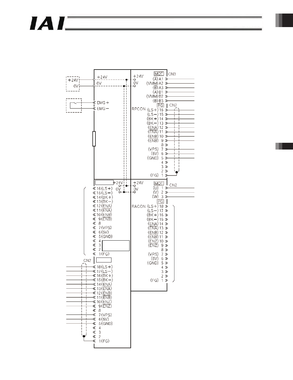
2.5 Connection Diagram
Shown below is a connection diagram of a ROBONET system comprising of a RPCON and a RACON connected to a simple
absolute R unit.
24-V power supply
Terminal block
Emergency stop circuit
RPCON
encoder cable port
RACON
encoder cable
(CB-ACS-PA***)
Gateway R unit
Field network
connector
PG (white)
Simple
absolute R unit
PG (red)
Motor cable (CB-RCP2-MA***)
RPCON encoder cable (CB-RCP2-PA***)
Motor cable (CB-ACS-MA***)
RACON encoder cable port
(Simple absolute R unit not connected)
-35-