Part 1 specification – IAI America REXT User Manual
Page 165
Part 1 Specification
Chapter 3 Gateway R unit
141
Part 1 Specification
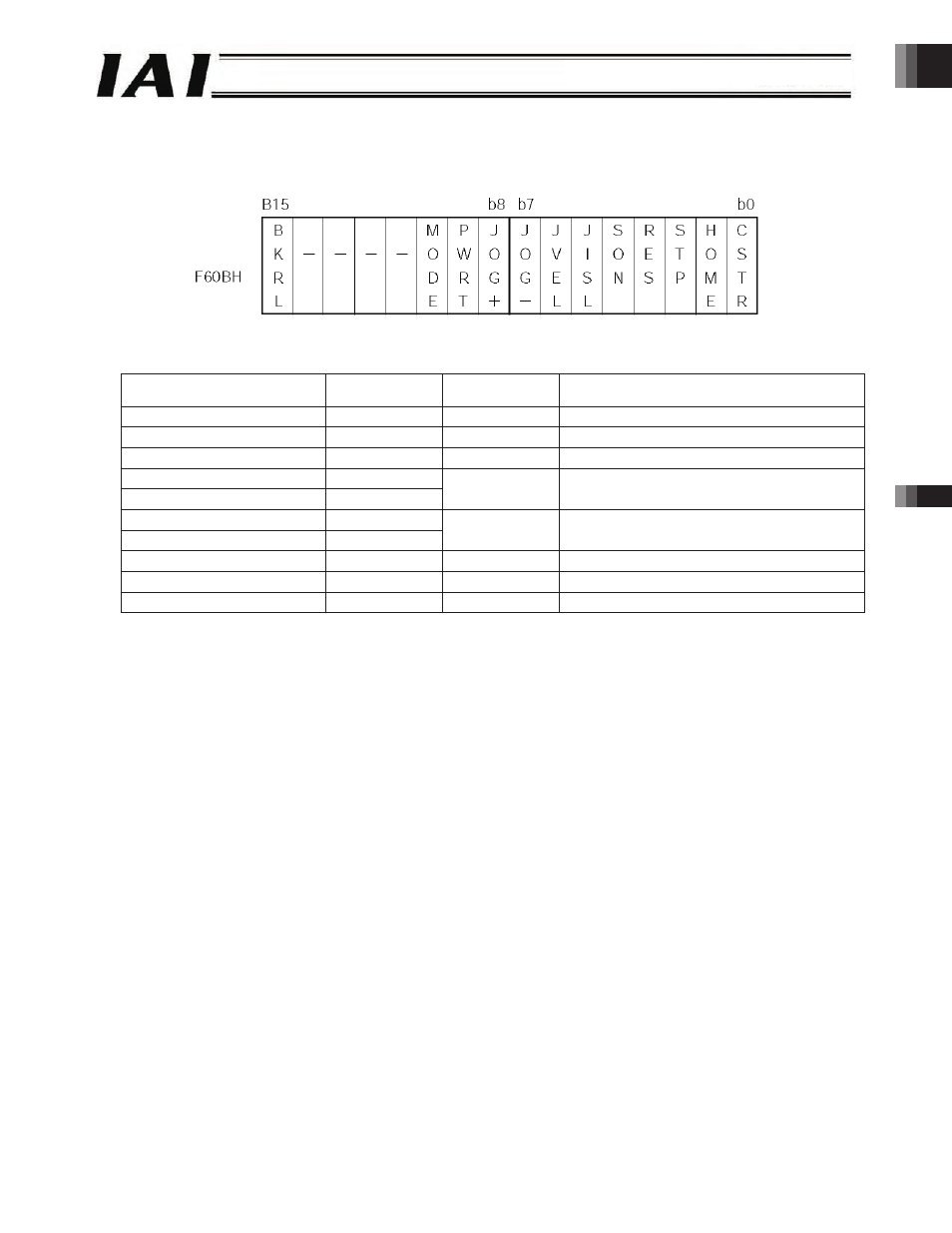
[3] Output control signals (Axis 0 = Positioner mode or simple direct mode)
An example of control signals of axis (0) is explained.
The configuration of the control signal register of axis (0) is shown below.
Servo ON Command (SON)
z
Query
Field name
RTU mode data
(8 bits)
Data length
(bytes)
Remarks
Header
None
-
Slave address
3F H
1
Fixed.
Function code
06 H
1
Starting address
(upper)
F6 H
Starting address
(lower)
0B H
2
Address of the control signal register of axis (0)
New data (data written) (upper)
00 H
New data (data written) (lower)
10 H
2
Error check
(CRC)
16 bits
2
Based on calculation result
Trailer
None
-
Total bytes
8
z
Response
If the data has been changed (written) successfully, the response is the same as the query.
z
Actual Example
Sent Query:
3F06F60B0010CE92
Received Response: 3F06F60B0010CE92
Address
-165-