Part 1 specification – IAI America REXT User Manual
Page 48
0
Part 1 Specification
Chapter 3 Gateway R unit
30
Part 1 Specification
3.5.3 MODE Switch
This switch is used to set the operation mode of the controller.
Status
Explanation
MANU
Manual operation: The ROBONET system can be operated using a teaching pendant or PC.
AUTO
Auto operation:
The ROBONET system is controlled via field network communication.
3.5.4 TP Connector
A connector used exclusively for connecting a teaching pendant or PC.
Connector: TCS7587-0121077 (by Hosiden)
3.5.5 User Setting Switches
These switches are used to set the operation mode of the Gateway R unit.
Normally SW3 and SW4 should remain OFF (they should be in the left positions). Do not change the settings of these
switches.
Explanation
SW No.
CC-Link
DeviceNet
Profibus
RS485SIO
SW4
Always OFF
SW3
Always OFF
SW2
Always OFF
Endian *2
ON: SIO through mode
OFF: Modbus gateway mode
SW1
When this switch is set to ON, the TP enable switch signal is effective.
*1 SW1 to SW4 are ON when set to the right side, and OFF when set to the left side.
*2 Remote I/O endian
ON
Little endian (LSB first)
PLC by Mitsubishi, Omron, etc.
OFF
Big endian (MSB first)
PLC by Siemens
3.5.6 ROBONET Communication Connector
This connector is used to connect a Modbus communication line, emergency stop signal, etc., to the axis controller unit.
Connection is made using the ROBONET communication connection circuit board supplied with the axis controller unit.
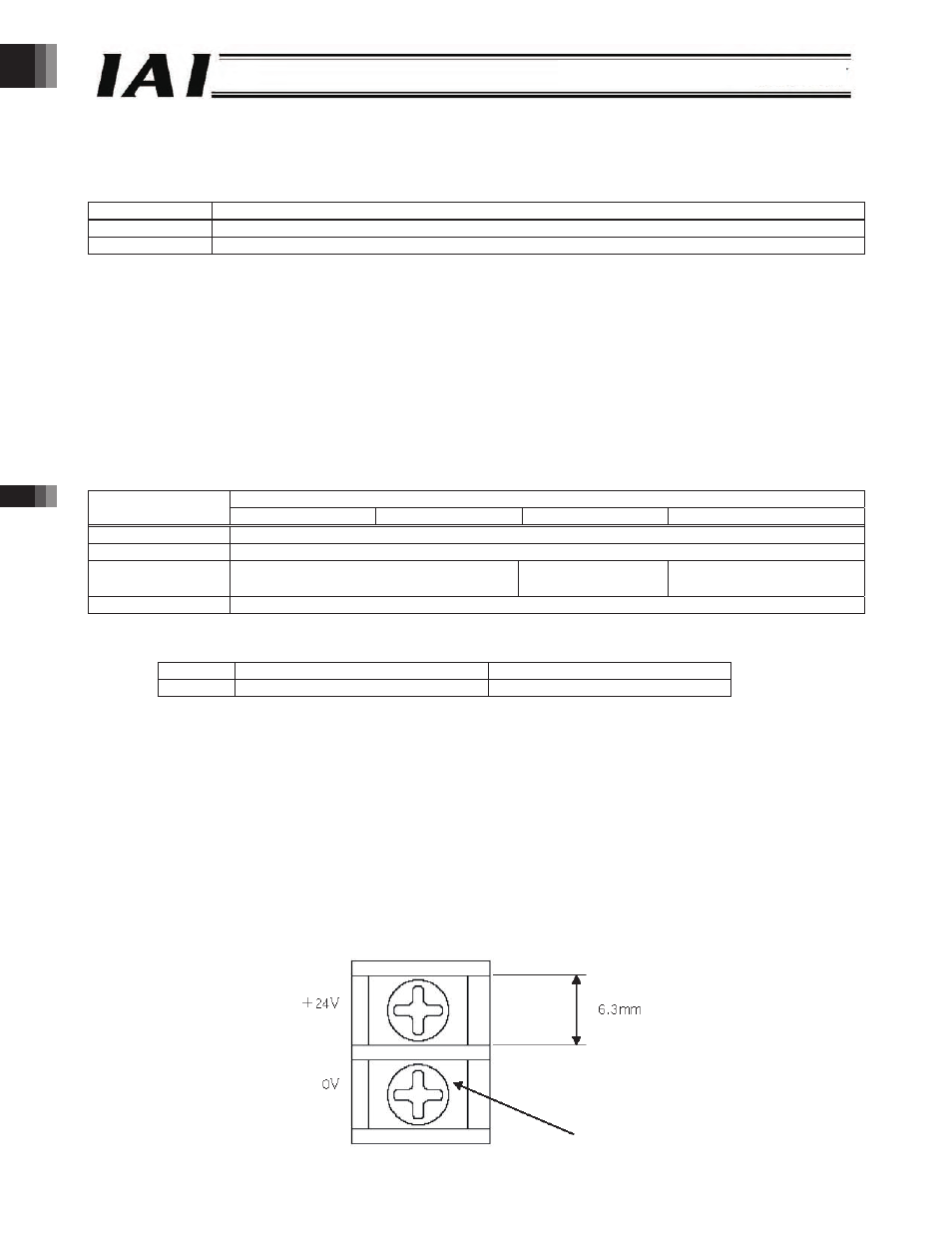
3.5.7 Power-supply Input Terminal Block
24-VDC power is input to this terminal block.
To supply power, connect the +24-V side and 0-V side to the power-supply input terminal block of the adjoining axis controller
unit using the power-supply connection plate supplied with the controller.
11. M3 screw
M3 screw
-48-