Part 1 specification – IAI America REXT User Manual
Page 69
Part 1 Specification
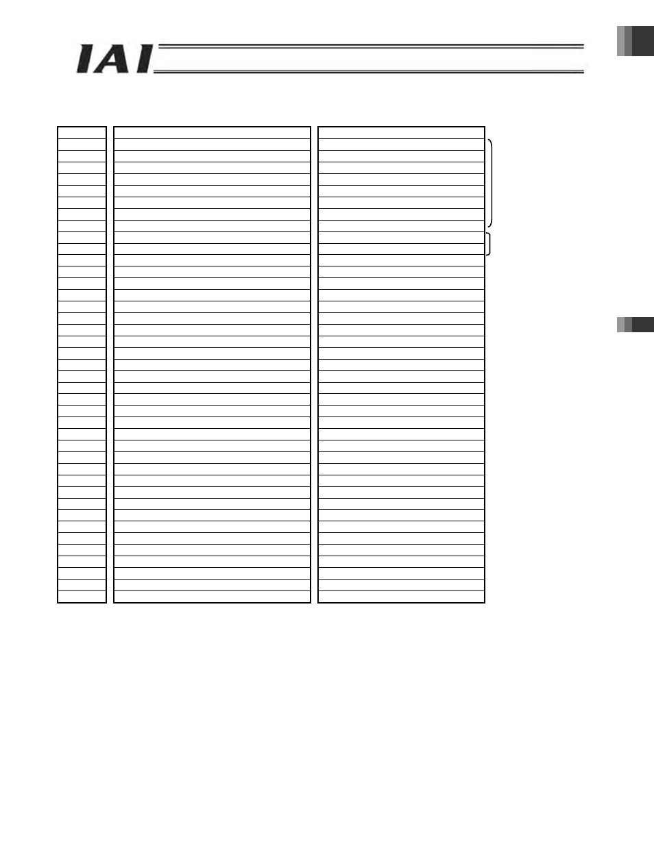
■ Example of overall EtherNet/IP address configuration (Positioner 2 mode and solenoid valve modes 1, 2)
An example where 16 axes in the positioner 2 mode and solenoid valve modes 1, 2 are connected is shown.
PLC output
ROBONET
ROBONET
PLC input
Relative byte *
Upper byte
Lower byte
Upper byte
Lower byte
0
Gateway control signal 0
Gateway status signal 0
2
Gateway control signal 1
Gateway status signal 1
Each byte is a fixed
8-word area.
4
Request command
Response command
6
Data 0
Data 0
8
Data 1
Data 1
10
Data 2
Data 2
12
Data 3
Data 3
14
(This area cannot be used.)
(This area cannot be used.)
16
(Axis 0) Command position number
(Axis 0) Completed position number
Each area consists of 2
words.
18
(Axis 0) Control signal
(Axis 0) Status signal
20
(Axis 1) Command position number
(Axis 1) Completed position number
22
(Axis 1) Control signal
(Axis 1) Status signal
24
(Axis 2) Command position number
(Axis 2) Completed position number
26
(Axis 2) Control signal
(Axis 2) Status signal
28
(Axis 3) Command position number
(Axis 3) Completed position number
30
(Axis 3) Control signal
(Axis 3) Status signal
32
(Axis 4) Command position number
(Axis 4) Completed position number
34
(Axis 4) Control signal
(Axis 4) Status signal
36
(Axis 5) Command position number
(Axis 5) Completed position number
38
(Axis 5) Control signal
(Axis 5) Status signal
40
(Axis 6) Command position number
(Axis 6) Completed position number
42
(Axis 6) Control signal
(Axis 6) Status signal
44
(Axis 7) Command position number
(Axis 7) Completed position number
46
(Axis 7) Control signal
(Axis 7) Status signal
48
(Axis 8) Command position number
(Axis 8) Completed position number
50
(Axis 8) Control signal
(Axis 8) Status signal
52
(Axis 9) Command position number
(Axis 9) Completed position number
54
(Axis 9) Control signal
(Axis 9) Status signal
56
(Axis 10) Command position number
(Axis 10) Completed position number
58
(Axis 10) Control signal
(Axis 10) Status signal
60
(Axis 11) Command position number
(Axis 11) Completed position number
62
(Axis 11) Control signal
(Axis 11) Status signal
64
(Axis 12) Command position number
(Axis 12) Completed position number
66
(Axis 12) Control signal
(Axis 12) Status signal
68
(Axis 13) Command position number
(Axis 13) Completed position number
70
(Axis 13) Control signal
(Axis 13) Status signal
72
(Axis 14) Command position number
(Axis 14) Completed position number
74
(Axis 14) Control signal
(Axis 14) Status signal
76
(Axis 15) Command position number
(Axis 15) Completed position number
78
(Axis 15) Control signal
(Axis 15) Status signal
* Relative bytes represent relative byte addresses from the top of the gateway.
P
ar
t 1
S
p
ec
if
ica
tion
Ch
apt
er
3
G
atew
a
y
R
u
n
i
t
-69-