Part 2 startup chapter, Caution – IAI America REXT User Manual
Page 292
0
Part 2 Startup Chapter
Chapter 2 Mounting and Installation
268
Part 2 Startup Chapter
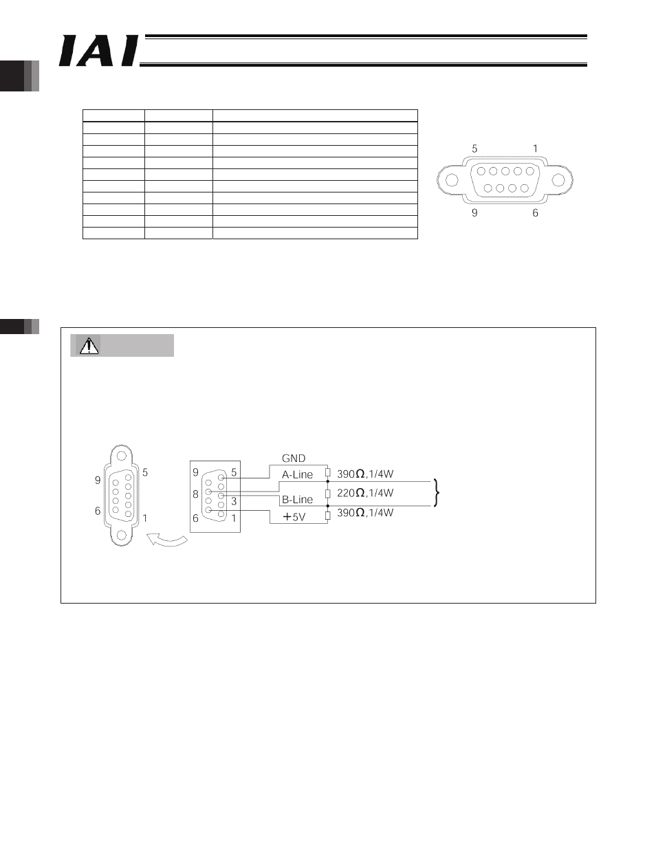
[6] The RGW-PR connector is a D-Sub, 9-pin Profibus-DP connector (female) recommended in the EN 50170 standard.
Network connectors are not provided.
Pin number Signal name
Explanation
1
NC
Not connected
2
NC
Not connected
3
B-Line
Communication line B (positive side)
4
NC
Not connected
5
GND
Signal ground
6
+5 V
+5-V output
7
NC
Not connected
8
A-Line
Communication line A (negative side)
9
NC
Not connected
Housing
Shield
Cable shield
Caution
The RGW-PR does not have terminal resistor setting switches. If the RGW-PR is connected at the end of a network,
connect a terminal resistor to the network connector or use a connector with terminal resistor, as specified below.
z
Connecting a terminal resistor
z
Profibus connector (with terminal resistor)
(Example) SUBCON-PLUS-PROFIB/AX/SC (Phoenix Contact)
Female connector
on RGW-PR end
Male connector on network
end (view from the side
opposite the insertion side)
Network wiring
-292-