Part 1 specification, 1 examples of overall address configuration – IAI America REXT User Manual
Page 61
Part 1 Specification
Chapter 3 Gateway R unit
41
Part 1 Specification
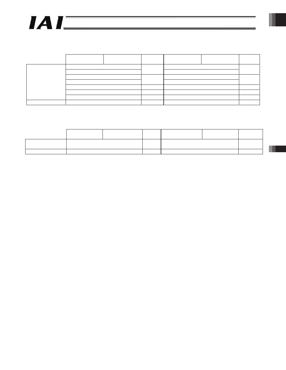
(3) Data Area Configuration in the Direct Numerical Specification Mode
PLC output Axis input
Axis output PLC input
Upper byte
Lower byte
Number
of words
Upper byte
Lower byte
Number
of words
Position data specification (L)*
Current position data (L)*
Position data specification (H)*
2
Current position data (H)*
2
Positioning band specification (L)*
Current electrical current (L)*
Positioning band specification (H)*
2
Current electrical current (H)*
2
Speed specification
1
Current speed data
1
Acceleration/deceleration specification
1
Cannot be used.
1
Direct numerical
specification area
Push-current limiting value
1
Alarm code
1
Control signal area
Control signal
1
Status signal
1
* (L) indicates the lower word of 2-word data, while (H) indicates the upper word of 2-word data.
(4) Structure of data fields in the positioner 2 mode, solenoid valve mode 1 and solenoid valve mode 2
Upper byte
Lower byte
Number
of words
Upper byte
Lower byte
Number of
words
Position
specification area
Command position number
1
Completed position number
1
Control signal area
Control signal
1
Status signal
1
3.7.1 Examples of Overall Address Configuration
Overall address configurations are shown based on a system where 12 4-word mode axes (positioner 1/simple direct mode)
and two 8-word mode axes (direct numerical specification mode) are connected.
For your information, the CC-Link and DeviceNet types are assigned by word addressing, while the Profibus and RS485 SIO
types are assigned by byte addressing.
(1) CC-Link
A configuration example using the CC-Link type is shown on the next page.
The eight words in the fixed area are assigned to bit registers (RX/RY), while the area of each axis is assigned to word
registers (RWr/RWw).
-61-