1 hardware configuration, 2 setting the input mode and control mode, 3 operation – NEC PD78214 User Manual
Page 93
64
µ
PD78214 Sub-Series
5.3.1 Hardware Configuration
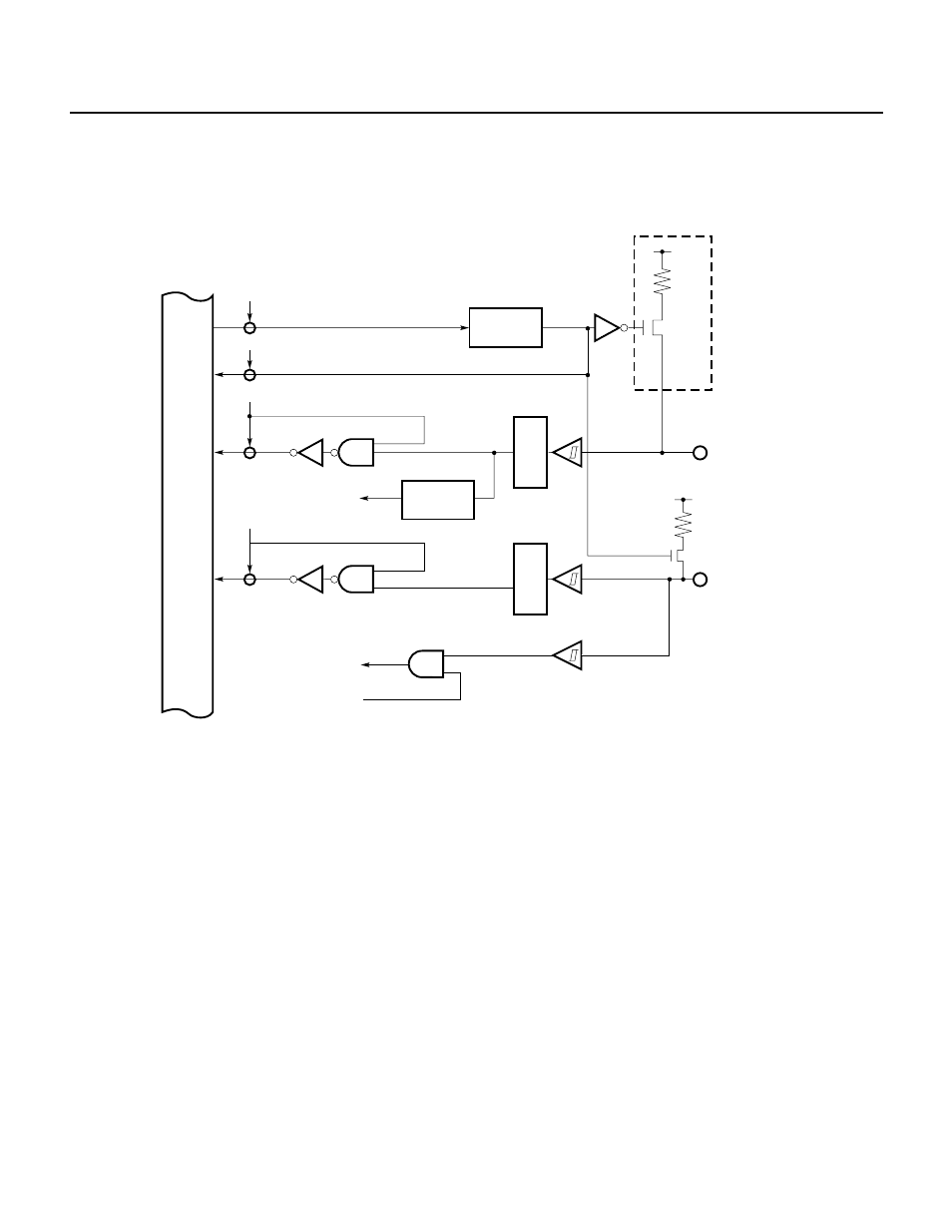
Fig. 5-6 shows the configuration of port 2
Fig. 5-6 Block Diagram of Port 2
Note P20 or P21 does not have a circuit enclosed in a dotted box.
5.3.2 Setting the Input Mode and Control Mode
Port 2 is an input-only port.
There is no register to specify an input mode for port 2. Port 2 is always ready to receive control signals. A register
such as a control register in the hardware is used to specify what control signal to receive.
5.3.3 Operation
Port 2 is an input-only port, and the level of each pin of it can be read and tested.
For P20 through P27, the level from which noise has be removed can be read and tested. See Chapter 11 for
removing noise.
WR
PUO
Pull-up resistor option register
PUO2
RD
PUO
Internal bus
RD
P2n
Noise
eliminator
RD
P27
Noise
eliminator
P2n
n = 0, 1, 2, ···, 6
V
DD
Edge
detector
Interrupt and
control signals
SI input
3-wire serial
I/O mode
P27