3 8-bit timer/counter 1 control registers, Chapter 7 timer/counter units – NEC PD78214 User Manual
Page 172
143
Chapter 7 Timer/Counter Units
7
7.2.3 8-Bit Timer/Counter 1 Control Registers
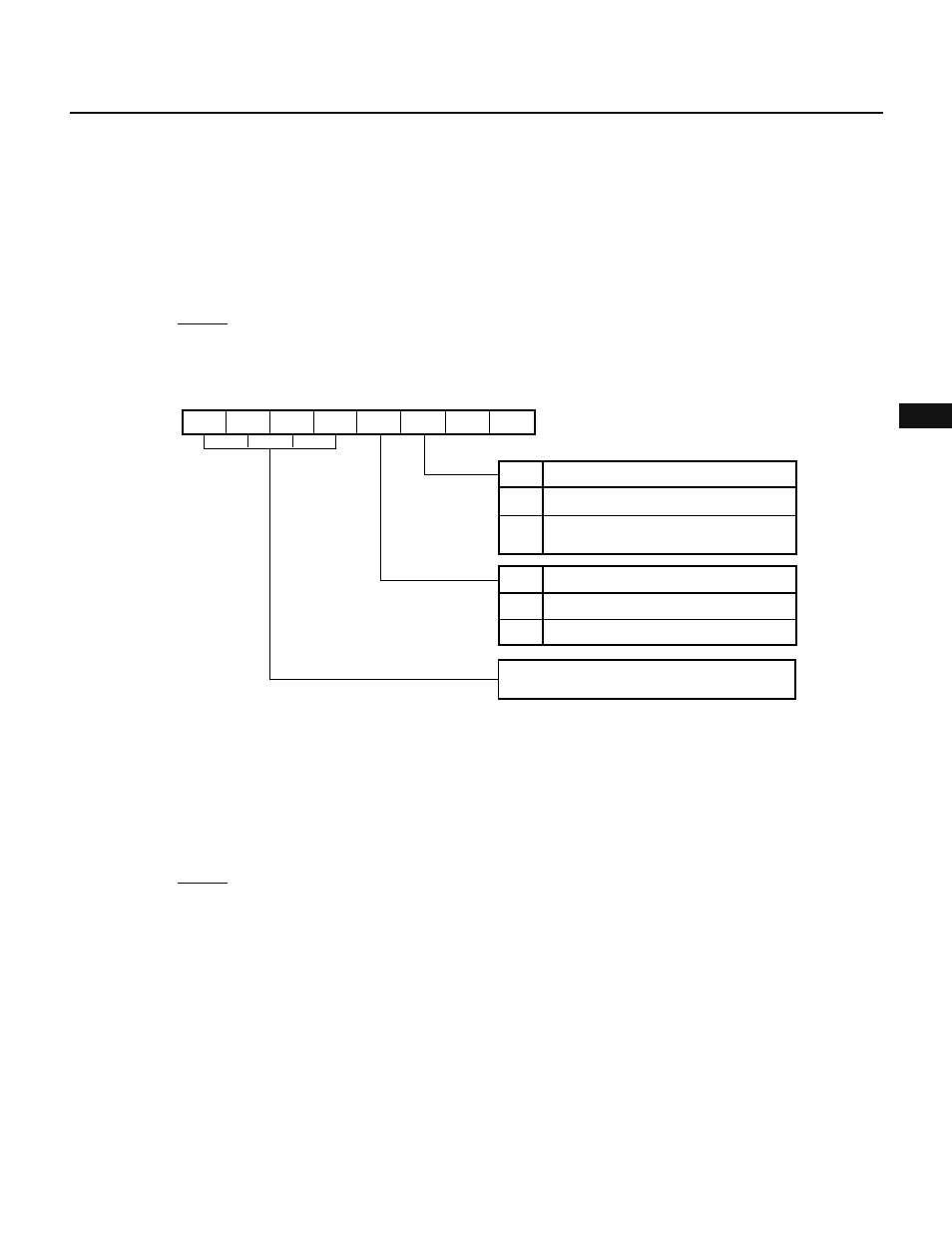
(1) Timer control register 1 (TMC1)
The TMC1 register is an 8-bit register for controlling the count operations of 8-bit timer 1 (TM1) and 8-bit timer
2 (TM2).
The lower 4 bits control the count operation of TM1 of 8-bit timer/counter 1. (The higher 4 bits control the count
operation of TM2 of 8-bit timer/counter 2.)
The TMC1 register allows both read and write operations using an 8-bit manipulation instruction. Fig. 7-44
shows the format of the TMC1 register.
When the RESET signal is applied, the TMC1 register is cleared to 00H.
Fig. 7-44 Format of Timer Control Register 1 (TMC1)
7
6
5
4
3
2
1
0
CE2
OVF2 CMD2
0
CE1
OVF1
0
0
TMC1
OVF1
0
1
1
0
CE1
TM1 overflow flag
Overflow does not occur
Overflow occurs
(countiing up from FFH to 00H)
TM1 counting control
Clears and stops counting
Enables counting
These bits control counting for 8-bit timer/
counter 2 (TM2) (see Fig. 7-67).
Remark The OVF1 bit can be reset only by software.
(2) Prescaler mode register 1 (PRM1)
The PRM1 register is an 8-bit register used to specify a count clock for 8-bit timer 1 (TM1) and 8-bit timer 2
(TM2).
The lower 4 bits are used to specify a count clock for TM1 of 8-bit timer/counter 1. (The higher 4 bits are used
to specify a count clock for TM2 of 8-bit timer/counter 2.)
The PRM1 register allows only write operation using an 8-bit manipulation instruction. Fig. 7-45 shows the
format of the PRM1 register.
When the RESET signal is applied, the PRM1 register is cleared to 00H.