Chapter 7 timer/counter units – NEC PD78214 User Manual
Page 162
133
Chapter 7 Timer/Counter Units
7
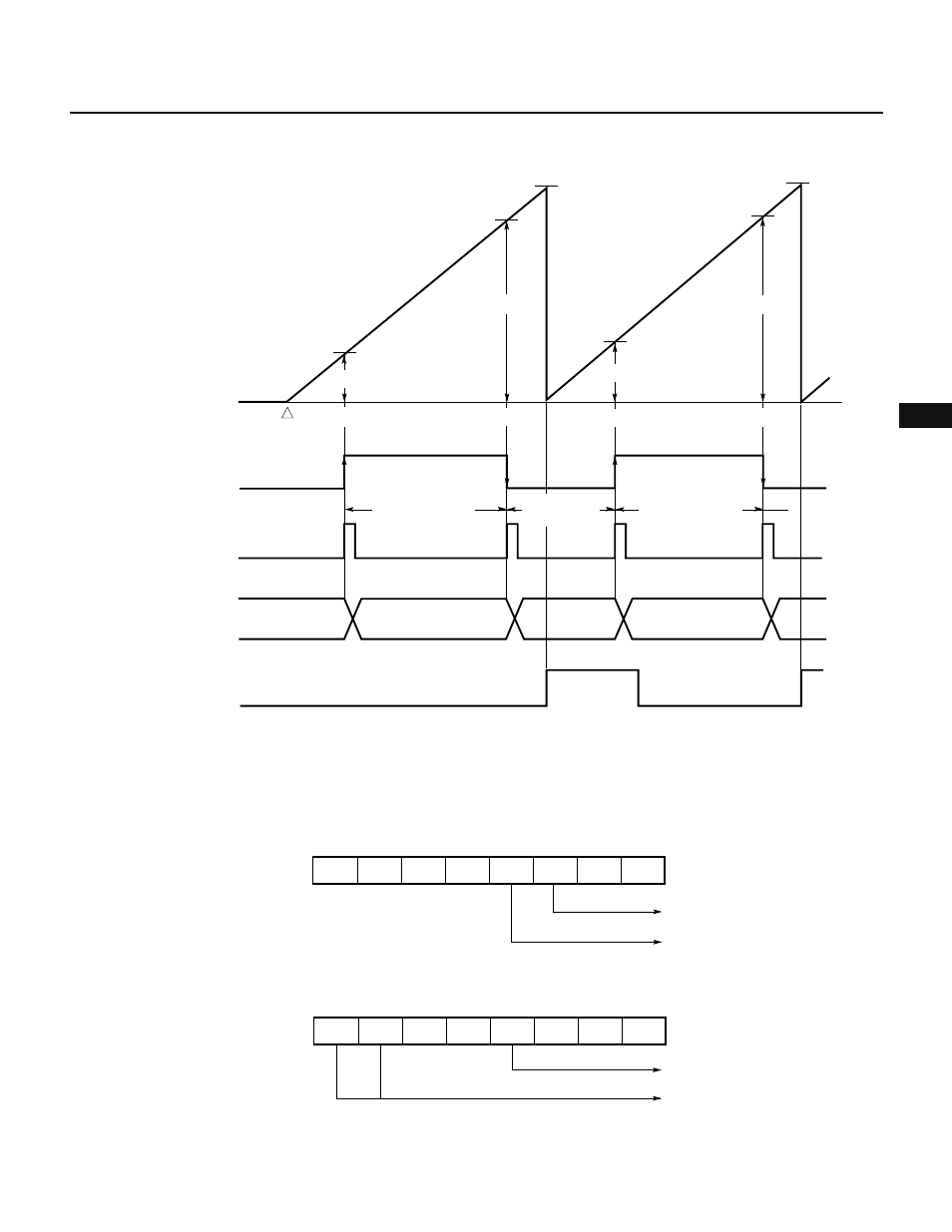
Fig. 7-31 Timing of Pulse Width Measurement
Remark D
n
: TM0 count value (n = 0, 1, 2, ...)
Fig. 7-32 Setting of Control Registers for Pulse Width Measurement
(a) Timer control register 0 (TMC0)
(b) Capture/compare control register 0 (CRC0)
7
6
5
4
3
2
1
0
0
0
0
0
0
0
0
1
CRC0
Disables clearing TM0
Both TO0 and TO1 are used for
toggle output
★
OVF0
CR02
TM0
count value
0H
D0
D1
Captured
Captured
(D1 – D0)
× 8/f
CLK
Captured
Count starts
CE0¨ 1
D0
D1
D2
D3
(D3 – D2)
× 8/f
CLK
(10000H – D1
+ D2)
× 8/f
CLK
FFFFH
FFFFH
INTP3
external input signal
INTP3
interrupt request
Cleared by software
Captured
D2
D3
7
6
5
4
3
2
1
0
0
0
0
0
0
0
1
TMC0
Overflow flag
Enables counting TM0
Ч