Chapter 10 clock synchronous serial interface – NEC PD78214 User Manual
Page 298
269
Chapter 10 Clock Synchronous Serial Interface
10
(2) Function to select a chip by its address
The master sends an address to select a slave chip.
(3) Wake-up function
Using the wake-up function (which can be set or released by software), a slave device can easily detect
whether it receives the address (chip select).
If the wake-up function is set, a serial reception interrupt (INTCSI) occurs only when the address is received.
While the master device is communicating with two or more devices, the CPUs of those slave devices which
are not selected can operate, independent of the serial communication.
(4) Acknowledge signal (ACK) control function
This function controls the acknowledge signal to check whether the serial data has been received.
(5) Busy signal (BUSY) control function
This function controls the busy signal that indicates that a slave device is busy.
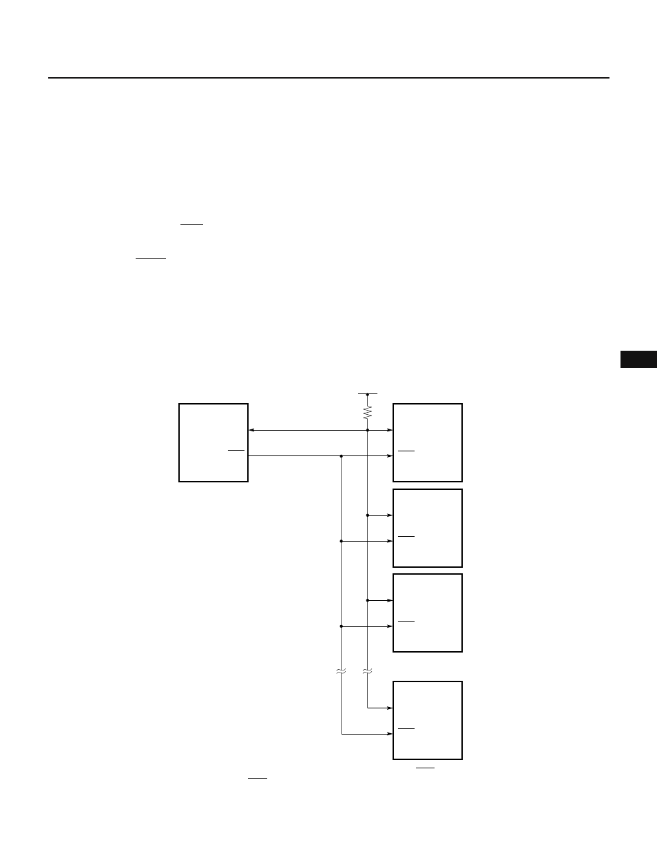
Fig. 10-7 shows a sample serial bus configured with CPUs having a serial interface conforming to SBI and
peripheral ICs.
In SBI mode, serial data bus pin SB0 functions as an open-drain output pin. The serial data bus lines are wired-
ORed. The serial data bus line requires a pull-up resistor.
Fig. 10-7 Sample Serial Bus Configured with SBI
SB0
SCK
SB0
SCK
SB0
SCK
SB0
SCK
SB0
SCK
Slave CPU
Address 1
Slave CPU
Address 2
Slave IC
Address 3
Slave IC
Address N
•
•
•
•
•
•
Master CPU
+V
DD
Serial data bus
Serial clock
Caution When switching the master and slave, the input and output of the serial clock line (SCK) are asynchronously switched between the
master and slave. The serial clock line (SCK) requires a pull-up resistor.