NEC PD78214 User Manual
Page 275
246
µ
PD78214 Sub-Series
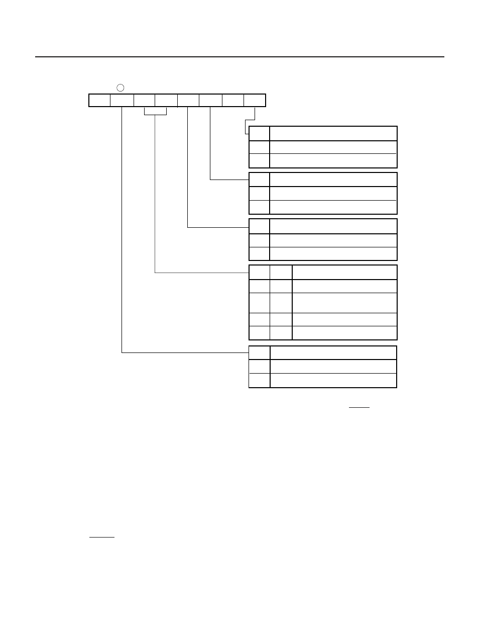
Fig. 9-2 Format of the Asynchronous Serial Interface Mode Register (ASIM)
Cautions 1. The asynchronous serial interface mode register (ASIM) must not be modified during transmission. If the ASIM register is
modified during transmission, further transmission becomes impossible (inputting the RESET signal resumes normal
operation).
Software can determine whether transmission is in progress, using the transmission completion interrupt (INTST) or the
interrupt request flag (STIF), which is set by the INTST.
2. If the ASIM register is modified during reception, the current and next receive data may be damaged. When changing the mode,
disable reception beforehand.
(2) Asynchronous serial interface status register (ASIS)
The ASIS register is a collection of flags that describe reception errors. A flag is set to 1 when a reception error
occurs. It is reset to 0 by reading data from the reception buffer. When the next data is received, the overrun
error flag (OVE) is set to 1, and the other error flags are reset to 0 (if this new data also contains an error, the
error flag corresponding to that error is set to 1).
Both 8-bit manipulation instruction and bit manipulation instruction can be used for the ASIS register, but
their use is limited to read operations.
When the RESET signal is input, the ASIS register is reset to 00H.
7
6
5
4
3
2
1
0
ASIM
1
RXE
PSI
PS0
CL
SL
0
SCK
SCK
0
1
SL
0
CL
Specifies serial clock
8-bit timer/counter 3 output
Baud rate generator output
Specifies character length for transmit/
receive data
1
1 bit
2 bits
0
1
7 bits
8 bits
Specifies stop bit for transmit data
PS1
PS0
0
0
1
1
1
0
1
0
No parity
Specifies parity bit for transmit/
receive data
Transmit: 0 parity append
Receive: No parity error
Odd parity
Even parity
RXE
Controls reception permission
Disables reception
0
1
Enables reception