NEC PD78214 User Manual
Page 189
160
µ
PD78214 Sub-Series
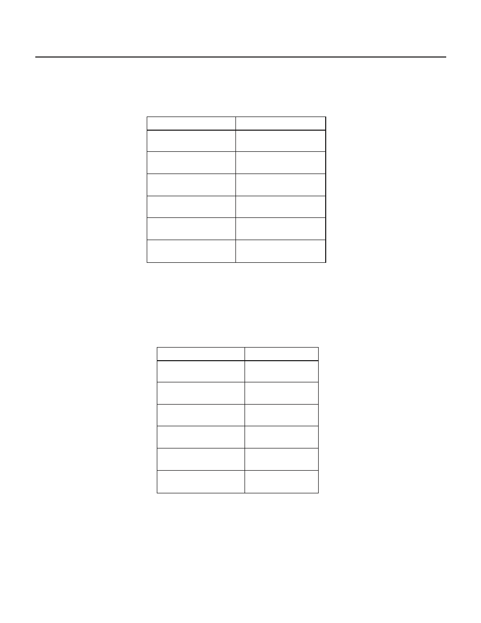
(2) Programmable square wave output
Eight-bit timer/counter 2 outputs a square wave separately on the TO2 and TO3 timer output pins.
Table 7-12 Programmable Square Wave Output Setting Range of 8-Bit Timer/Counter 2
Maximum pulse width
2
8
× 16/f
CLK
(683
µs)
2
8
× 32/f
CLK
(1.37 ms)
2
8
× 64/f
CLK
(2.73 ms)
2
8
× 128/f
CLK
(5.46 ms)
2
8
× 256/f
CLK
(10.9 ms)
2
8
× 512/f
CLK
(21.8 ms)
Minimum pulse width
16/f
CLK
(2.6
µs)
32/f
CLK
(5.3
µs)
64/f
CLK
(10.7
µs)
128/f
CLK
(21.3
µs)
256/f
CLK
(42.7
µs)
512/f
CLK
(85.3
µs)
The values in parentheses are based on f
CLK
= 6 MHz.
Caution The values in Table 7-12 assume the use of an internal clock.
(3) Pulse width measurement
Eight-bit timer/counter 2 measures the pulse width of a signal applied to the external interrupt input pin
INTP1.
Table 7-13 Pulse Width Measurement Range of 8-Bit Timer/Counter 2
Measurable pulse width
≤2
8
× 16/f
CLK
(683
µs)
≤2
8
× 32/f
CLK
(1.37 ms)
≤2
8
× 64/f
CLK
(2.73 ms)
≤2
8
× 128/f
CLK
(5.46 ms)
≤2
8
× 256/f
CLK
(10.9 ms)
≤2
8
× 512/f
CLK
(21.8 ms)
Resolution
16/f
CLK
(2.6
µs)
32/f
CLK
(5.3
µs)
64/f
CLK
(10.7
µs)
128/f
CLK
(21.3
µs)
256/f
CLK
(42.7
µs)
512/f
CLK
(85.3
µs)
The values in parentheses are based on f
CLK
= 6 MHz.