Chapter 10 clock synchronous serial interface – NEC PD78214 User Manual
Page 300
271
Chapter 10 Clock Synchronous Serial Interface
10
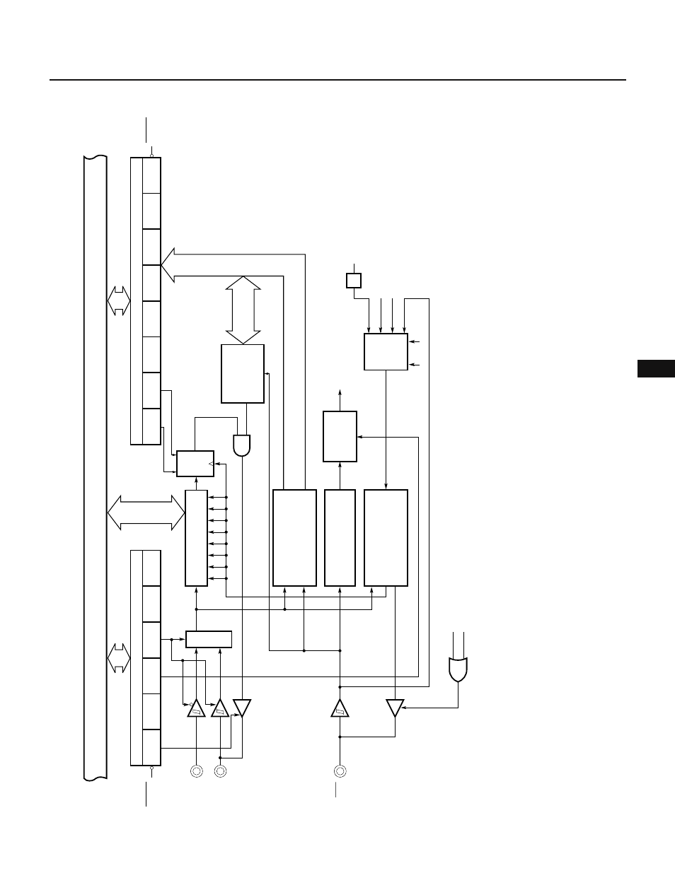
Fig. 10-9 Block Diagram of Clock Synchronous Serial Interface
Internal bus
D
CLS1
CLS0
f
CLK
/32
f
CLK
/8
INTCSI
Interrupt
signal
generator
circuit
Bus release/command/
acknowledge detector
circuit
Serial clock counter
Serial clock control
circuit
N-ch open-drain
output enabled
Selector
P32/SCK
P33/SO/SB0
P27/SI
RESET
CTXE
CRXE
WUP
MOD1
CLS1
CLS0
1/8
CSIM
ACKT
CMDD
RELD
CMDT
RELT
ACKE
ACKD
BSYE
1/8
SBIC
8
Shift register SIO
RESET
Busy/
acknowledge
output circuit
Q
SO latch
SET
CLEAR
CLS1
CLS0
MPX
8-bit timer/counter 3 output
1/2