5 application example – NEC PD78214 User Manual
Page 131
102
µ
PD78214 Sub-Series
6.5 APPLICATION EXAMPLE
This section describes an example of application in which P00 through P03 are used as a 4-bit real-time output port.
Each time TM1 for 8-bit timer/counter 1 coincides with the contents of CR10, the contents of the P0L are output
to P00 through P03. At this point, an interrupt occurs, and the interrupt handling routine for this interrupt sets the
next data to be output and determines the timing at which the output is to change (see Fig 6-6).
See Section 7.2 for how to use timer/counter 1.
Fig. 6-7 shows the data to be set in the control register, Fig. 6-8 illustrates the procedure to set the data, and Fig.
6-9 is a flowchart of the interrupt handling routine.
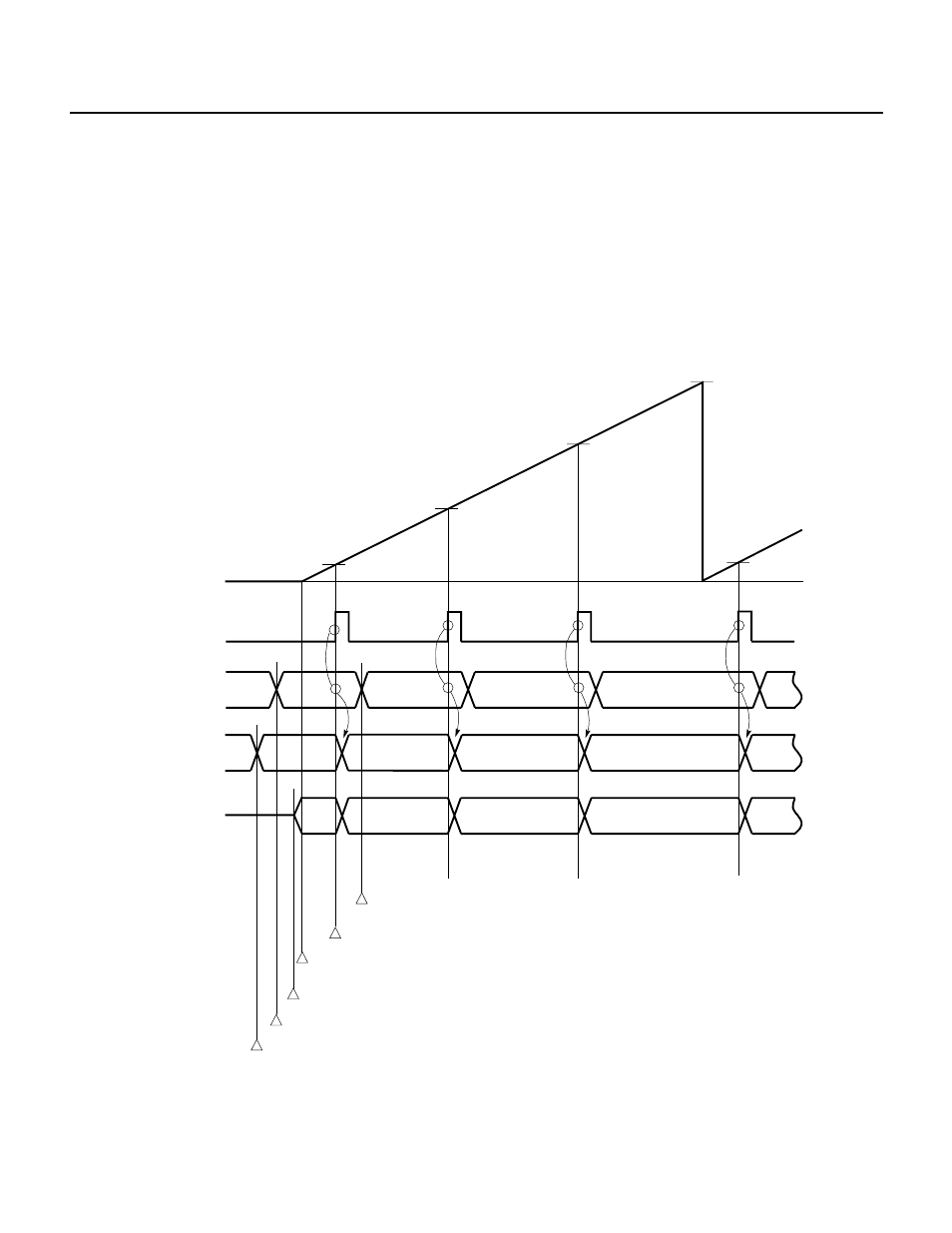
Fig. 6-6 Real-Time Output Port Operation Timing
8-bit timer/
counter 1
0H
INTC10
interrupt request
CR10
CR10
CR10
CR10
FFH
D01
D02
D03
D04
D00
D01
D02
D03
D03
D02
D01
D00
Hi-z
Buffer register
P0L
Output latches
P00-P03
Output latches
P00-P03
Change the contents of the buffer register and compare register by
an INTC10 interrupt.
Transfer the contents of the buffer register to the output latch when the contents
of TM1 coincide with those of CR10.
Timer starts
Turn the output buffer on
Set data to be output next in the buffer register P0L
Set data output first in the output latches of pins P00 to P03