1 hardware configuration, 2 setting the input/output mode and control mode, Chapter 5 port functions – NEC PD78214 User Manual
Page 90
61
Chapter 5 Port Functions
5
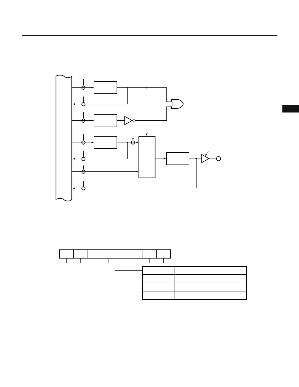
5.2.1 Hardware Configuration
Fig. 5-2 shows the hardware configuration of port 0.
Fig. 5-2 Configuration of Port 0
5.2.2 Setting the Input/Output Mode and Control Mode
The port 0 mode register (PM0) sets the I/O mode of port 0, as shown in Fig. 5-3. This register is set by an 8-bit
data transfer instruction. (It can neither manipulated in bit units nor read-accessed).
Fig. 5-3 Port 0 Mode Register Format
PM07
7
PM06
6
PM05
5
PM04
4
PM03
3
PM02
2
PM01
1
PM00
0
PM0
Other than above
FFH
00H
PM0
Cannot be set
High-impedance state (output buffer OFF)
Output mode (output buffer ON)
Specifies P0n pin mode (n = 0 to 7)
(FFH when RESET is input)
To use port 0 as a real-time output port, it is necessary to set the P0LM and P0HM bits of the real-time output port
control register (RTPC) to 1.
When the P0LM and P0HM bits are set, the output buffer for each pin is turned on, and the contents of the output
latch are output to the pin, regardless of the contents of the PM0.
WR
RTPC
Real-time output port control register
P0LM
(P0HM)
WR
PM0
Port 0 mode register
PM0n
(PM0m)
WR
P0L
Buffer register
P0Ln
(P0Hm)
RD
RTPC
RD
P0L
RD
IN
Output latch
P0n
(P0m)
WR
OUT
Trigger
Selector
P0n
(P0m)
n = 0, 1, 2, 3
m = 4, 5, 6, 7
Internal bus