6 functions – NEC PD78214 User Manual
Page 47
18
µ
PD78214 Sub-Series
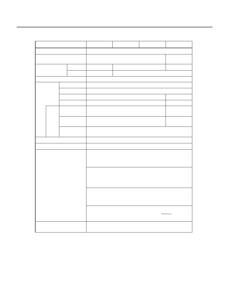
1.6 FUNCTIONS
Item
Input pins
Output pins
I/O pins
Total
Connected to a
pull-up resistor
Driving a LED
directly
Driving a
transistor directly
65
µPD78213
µPD78212
µPD78214
µPD78P214
Real-time output ports
General-purpose registers
Timer/counters
333 ns
500 ns
8K bytes
16K bytes
None
384 bytes
512 bytes
28
10
54
36
8
16
0
34
16
14
12
64KB for program and 1MB for data
Two four-bit ports or one eight-bit port
Four banks of eight eight-bit registers (memory mapping)
Number of basic instructions (mnemonics)
Minimum instruction execution
time (when operating at 12 MHz)
Capacity of
internal memory
Memory area
ROM
RAM
Special-function
pins
Note
16-bit timer/counter, consisting of
one timer register, one capture
register, and two compare registers.
Pulse output possible (toggle
output or PWM/PPG output)
8-bit timer/counter unit 1, consisting of
one timer register, one capture/
compare register, and one compare
register
Pulse output possible (two
four-bit, real-time outputs)
8-bit timer/counter unit 2, consisting
of one timer register, one capture
register, and two compare registers.
Pulse output possible (toggle
output or PWM/PPG output)
8-bit timer/counter unit 3, consisting
of one timer register and one
compare register
One-channel UART (special baud rate generator incorporated)
One-channel CSI (three-wire serial I/O, SBI)
Serial interface
Number of
I/O pins
Note The number of I/O pins includes special-function pins.