Chapter 12 interrupt functions – NEC PD78214 User Manual
Page 370
341
Chapter 12 Interrupt Functions
12
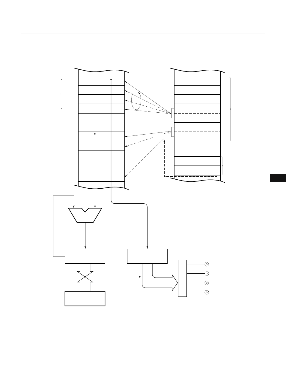
Fig. 12-33 Block Diagram 2 for Automatic Addition Control Plus Ring Control
(with the Output Timing Varied by Phase 2 Excitation)
MSC
FF
–1
Ring counter (RC)
04
–1
Modulo register (MR)
04
MPDL
00
+1
MPDH
B0
MPTL
00
MPTH
B1
Mode register
EE
Channel pointer
CF
Macro service
control word
Macro service
channel
•
•
•
D0
D1
D7
∆t0
•
•
•
Compare register
CR10
P00
Output latch
Coincidence
INTC10
P0
8-bit timer/counter 1
TM1
Addition
Buffer register
P0L
•
•
•
0B000
0B001
0B007
•
•
•
Output data
(4 pieces)
Output timing: 0B100
64K memory space
P01
P02
P03
To stepper motor
0FECFH
•
•
•
∆t1
∆tFF
Macro service control word
+1