NEC PD78214 User Manual
Page 347
318
µ
PD78214 Sub-Series
3. “Peripheral RAM” corresponds to the internal RAM at addresses 0FC80H through 0FDFFH (for the
µPD78212, 0FD80H through
0FDFFH).
4. 1 clock = 1/f
CLK
(167 ns at 12 MHz).
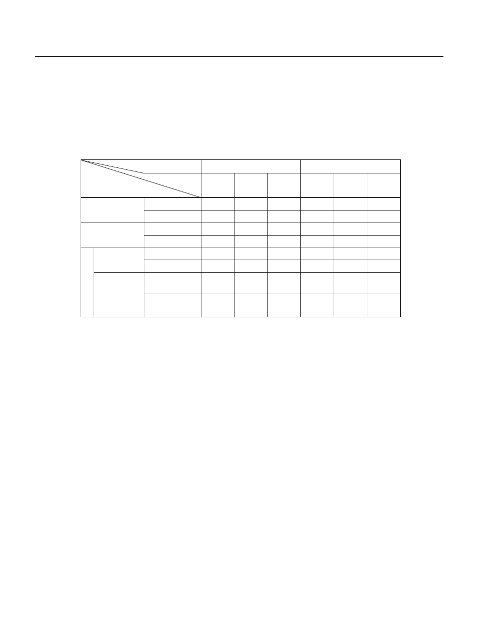
(3) Macro service processing time
The time required to process a macro service varies, depending on the type of the macro service, as listed in
Table 12-6.
Table 12-6 Macro Service Processing Time
Note
(Unit: Clock)
Memory
—
—
30
—
37
41
42/47
46/51
Memory to SFR
SFR to memory
Memory to SFR
SFR to memory
Data transfer
Automatic addition
Data transfer
Automatic addition
Internal
ROM
Internal
RAM
External
memory
19
20
29
31
35
39
40/45
44/49
—
—
31 + w
33 + w
39 + 2w
43 + 2w
44 + 2w/
49 + 2w
48 + 2w/
53 + 2w
—
—
32 + w
—
39 + w
43 + w
44 + w/
49 + w
48 + w/
53 + w
Internal
ROM
Internal
RAM
External
memory
21 + w
22 + w
31 + w
33 + w
37 + w
41 + w
42 + w/
47 + w
46 + w/
51 + w
—
—
33 + 2w
35 + 2w
41 + 3w
45 + 3w
46 + 3w/
51 + 3w
50 + 3w/
55 + 3w
C
Internal ROM fetch
External ROM fetch
Program fetch
Without ring
control
macro service
processing type
With ring
control
A
B
(w = number of wait cycles)
Note The time listed here does not include the time that elapses before the current instruction is completed or the time required to identify
the priority of the interrupt request.
Remarks 1. The values in the “Internal ROM fetch” column apply when the IFCH bit of the memory expansion mode register (MM) is 1. If
the IFCH bit is 0, see the “External ROM fetch” column.
2. The values in the “Internal RAM” column apply when an internal RAM at 0FE00H through 0FEFFH is used. If other areas in the
internal RAM are used, the values in the “External memory” column apply after w is reset to 0.
3. The values on the right of “/” apply when the ring counter is 0. The values on the left of “/” apply when the ring counter is other
than 0.
4. 1 clock = 1/f
CLK
(167 ns at 12 MHz)
5. For types A and B, an additional wait time of up to 15 clocks is inserted. See (8) of Section 7.5.1 and Table 7-20 in Chapter 7 for
details.
6. The number of clocks for type C does not include wait states inserted for access to the CR10 or CR11. If the wait time is inserted,
the values in the list must be increased by one clock.