Chapter 2 pin functions – NEC PD78214 User Manual
Page 58
29
Chapter 2 Pin Functions
2
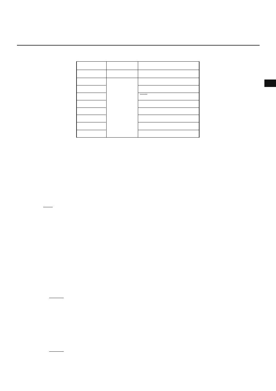
Table 2-2 Port 3 Operating Mode (n = 0 to 7)
P30
P31
P32
P33
P34
P35
P36
P37
RxD input
TxD output
SCK input/output
SO output/SB0 input/output
TO0 output
TO1 output
TO2 output
TO3 output
Mode
PMC3 setting
Port mode
PMC3n = 0
Control signal I/O mode
PMC3n = 1
I/O port
(a) Port mode
Pins for which port mode is specified by the PMC3 can be used independently as input or output pins by
specifying the port-3 mode register (PM3).
(b) Control signal I/O mode
Each pin can be used as a control signal pin by specifying the PMC3 register.
(i) RxD (receive data)
Serial data input for asynchronous serial interface
(ii) TxD (transmit data)
Serial data output for asynchronous serial interface
(iii) SCK (serial clock)
Serial clock input or output for synchronous serial interface
(iv) SO (serial output)/SBO (serial bus)
Serial data output (when three-wire serial I/O mode is used), or serial bus input or output in SBI mode
(v) TO0 to TO3 (timer output)
Timer outputs
(4) P40-P47 (port 4): Tristate inputs/outputs
Port 4, an eight-bit I/O port with output latches, is provided with software-programmable pull-up resistors and
can directly drive LEDs. Its pins can be collectively used as input or output pins by specifying the memory
expansion mode register (MM).
It acts as a time-multiplexed address/data bus (AD0 to AD7) when external memory or I/O devices are
expanded.
In the case of the
µPD78213, it acts as a time-multiplexed address/data bus (AD0 to AD7).
When the RESET signal is input, the output of port 4 becomes high impedance, such that it functions as an
input port, resulting in the contents of the output latches becoming undefined.
(5) P50 to P57 (port 5): Tristate inputs/outputs
Port 5, an eight-bit I/O port with output latches, is provided with software-programmable pull-up resistors and
can directly drive LEDs. Its pins can be used independently as input or output pins by specifying the port-5
mode register(PM5) accordingly.
It acts as an address bus (A8 to A15) when external memory or I/O devices are expanded.
In the case of the
µPD78213, it functions as an address bus (A8 to A15).
When the RESET signal is input, the output of port 5 becomes high impedance, such that it functions as an
input port, resulting in the contents of the output latches becoming undefined.