NEC PD78214 User Manual
Page 173
144
µ
PD78214 Sub-Series
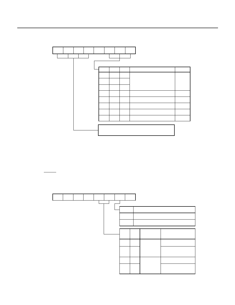
Fig. 7-45 Format of Prescaler Mode Register 1 (PRM1)
7
6
5
4
3
2
1
0
PRM1 PRS23
0
PRS12
0 0 0
0 0 1
0 1 0
0 1 1
1 0 0
1 0 1
1 1 0
1 1 1
PRS10
PRS11
Specification of count clock [Hz]
f
CLK
/16
f
CLK
/32
f
CLK
/64
f
CLK
/128
f
CLK
/256
f
CLK
/512
85.3 s
42.7 s
21.3 s
10.7 s
5.3 s
2.6 s
Resolution
f
CLK
= 6 MHz
These bits specify the count clock supplied to
8-bit timer/counter 2 (TM2) (see Fig. 7-68).
PRS22 PRS21 PRS20
PRS12 PRS11 PRS10
µ
µ
µ
µ
µ
µ
Remark f
CLK
: System clock frequency
(3) Capture/compare control register 1 (CRC1)
The CRC1 register is used to specify the operation of the CR11 capture/compare register and the condition for
enabling the clear operation of 8-bit timer 1 (TM1).
The CRC1 register allows only write operation using an 8-bit manipulation instruction. Fig. 7-46 shows the
format of the CRC1 register.
When the RESET signal is applied, the CRC1 register is cleared to 00H.
Fig. 7-46 Format of Capture/Compare Control Register 1 (CRC1)
7
6
5
4
3
2
1
0
CRC1
0
0
0
0
CLR11
CM
CLR10
0
Clearing TM1 when TM1 coincides with CR10
0
1
CLR10
Disabled
Enabled
CLR11
CM
0
1
0
1
0
0
1
1
Operation speci-
fication of the
CR11 register
Compare
register
Clearing TM1
Capture
register
Enabled (when contents
of TM1 register coincides
with those of CR11 register)
Disabled
Disabled
Enabled (when contents
of TM1 register is captured
to the CR11 register)