2 setting the i/o mode and control mode, Chapter 5 port functions – NEC PD78214 User Manual
Page 100
71
Chapter 5 Port Functions
5
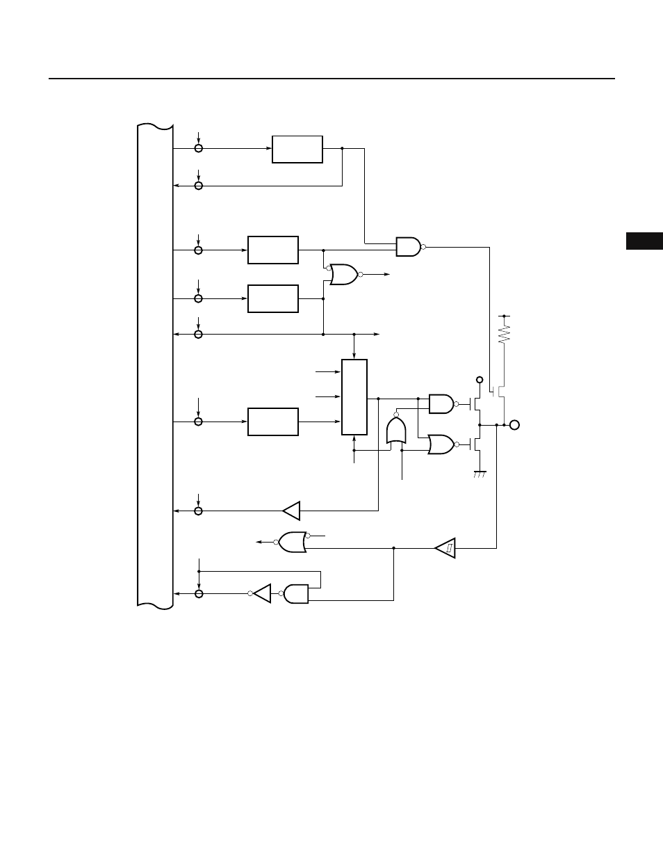
Fig. 5-13 Block Diagram of P33 (Port 3)
★
5.4.2 Setting the I/O Mode and Control Mode
The port 3 mode register (PM3) can put each pin of port 3 in either the input or output mode independently of the
other pins, as shown in Fig. 5-14.
The PM3 register is loaded with data using an 8-bit data transfer instruction; it cannot be bit-manipulated or read-
accessed.
In addition to I/O port functions, each pin of port 3 works as a control signal pin. As shown in Fig. 5-15, the port
3 mode control register (PMC3) can specify the mode of control for each pin.
Internal bus
RD
OUT
P33
V
DD
RD
IN
RD
PUO
WR
PUO
Pull-up resistor option register
PUO3
WR
PM33
Port 3 mode register
PM33
WR
PMC33
PMC33
RD
PMC33
WR
P33
P33
Selector
Output latch
SB0 output
SO output
PMC33
Output disable
Output
disable
SBI mode
PMC33
SB0 input