Chapter 7 timer/counter units – NEC PD78214 User Manual
Page 224
195
Chapter 7 Timer/Counter Units
7
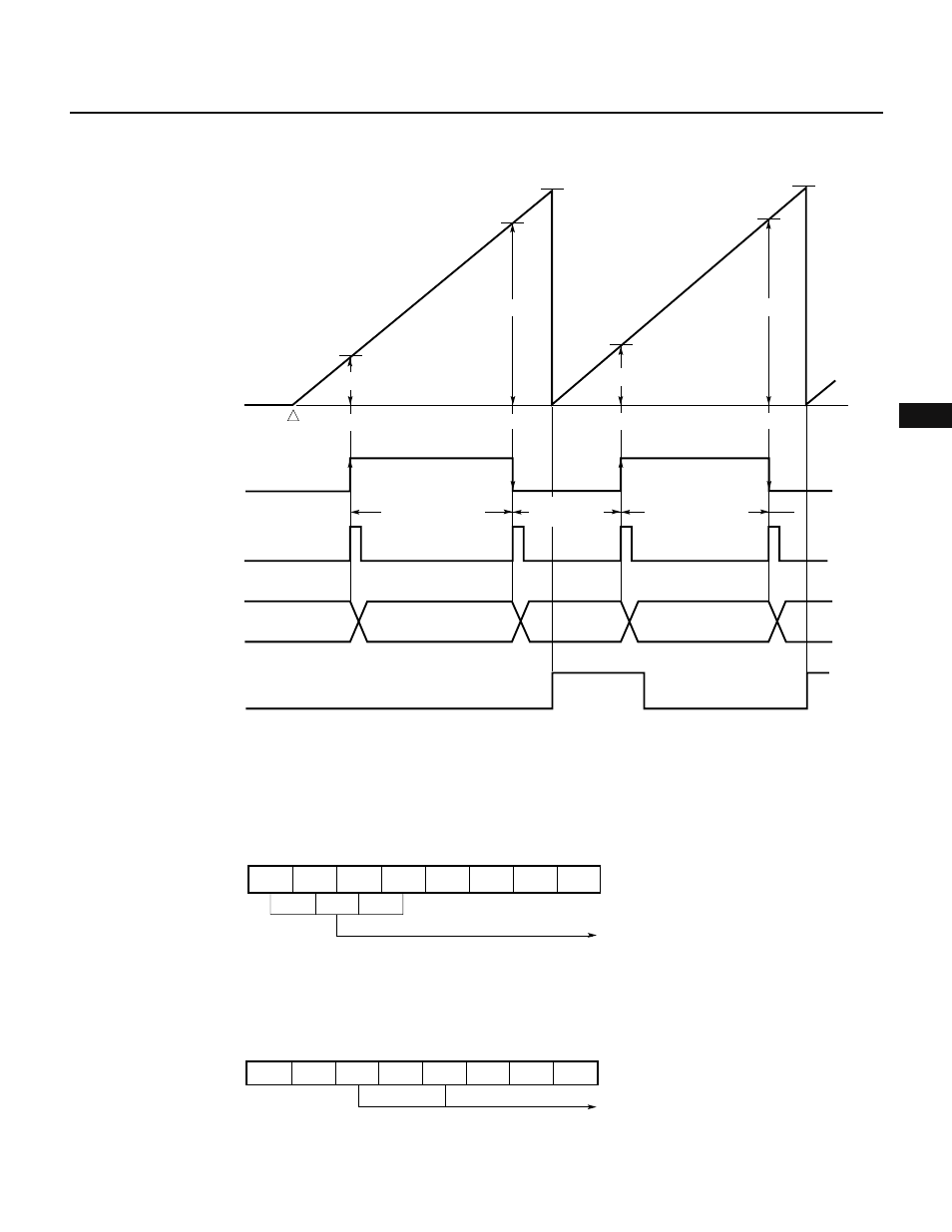
Fig. 7-103 Timing of Pulse Width Measurement
Remark D
n
: TM2 count value (n = 0, 1, 2, ...)
Fig. 7-104 Setting of Control Registers for Pulse Width Measurement
(a) Prescaler mode register 1 (PRM1)
(b) Capture/compare control register 2 (CRC2)
7
CRC2
0
0
6
5
4
3
2
1
0
0
1
0
0
0
0
Disables clearing TM2
7
6
5
4
3
2
1
0
PRS23
×
0
PRM1
Specifies count clock
(x/f
CLK
; where x = 16, 32, 64,
128, 256, 512,
or external clock)
PRS22 PRS21 PRS20
Ч
Ч
OVF2
Capture register (CR22)
TM2
count value
0H
Captured
Captured
(D1 – D0)
× X/f
CLK
Captured
Count starts
D0
D1
D2
D3
(D3 – D2)
× X/f
CLK
(100H – D1+
D2)
× X/f
CLK
D3
FFH
FFH
INTP1
external input signal
INTP1
interrupt request
Cleared by software
Captured
↑
D1
D0
D2