6 port 5, 1 hardware configuration, 2 setting the i/o mode and control mode – NEC PD78214 User Manual
Page 109
80
µ
PD78214 Sub-Series
5.6 PORT 5
Port 5 is an 8-bit I/O port with an output latch. The port 5 mode register (PM5) can put each bit of this port in either
the input or output mode, independently of the other bits. Each pin has a software-programmable built-in pull-
up resistor, and can drive an LED directly.
When an external memory or I/O device is expanded, P50 through P57 function as an address bus (AD8 through
AD15). For the
µPD78213, P50 through P57 function only as an address bus (AD8 through AD15).
When the RESET signal is input, port 5 becomes an input port (high output impedance), and the contents of the
output latch become undefined.
5.6.1 Hardware Configuration
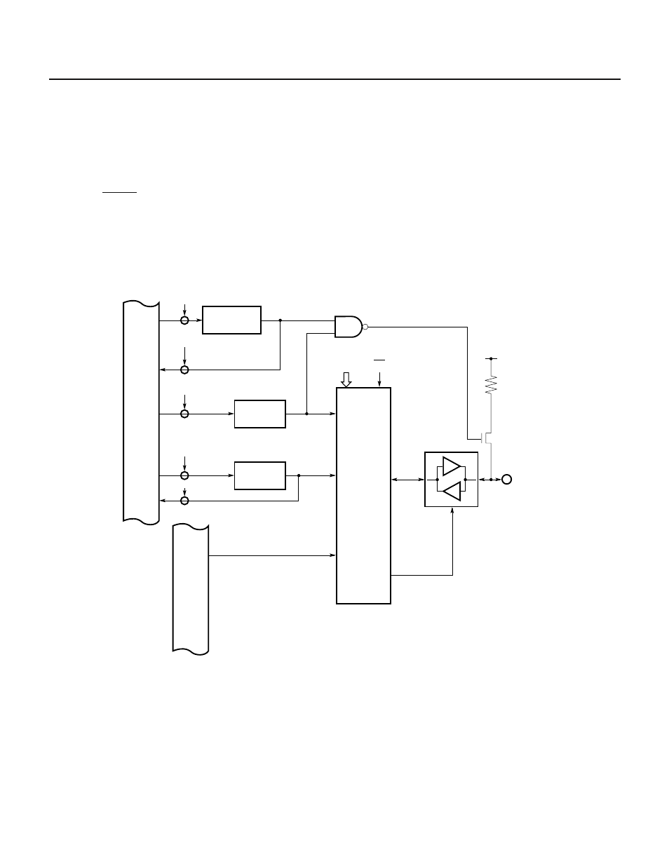
Fig. 5-27 shows the hardware configuration of port 5.
Fig. 5-27 Block Diagram of Port 5
5.6.2 Setting the I/O Mode and Control Mode
The port 5 mode register (PM5) can put each pin of port 5 in either the input or output mode independently of the
other pins, as shown in Fig. 5-28. The PM5 register is loaded with data using an 8-bit data transfer instruction; it
cannot be bit-manipulated or read-accessed.
The memory expansion mode register (MM, see Fig. 13-1) can specify the control mode of port 5, as listed in Table
5-6.
Internal data bus
WR
PUO
Pull-up resistor option register
WR
PM5n
RD
PUO
Port 5 mode register
P5n
n = 0 to 7
V
DD
MM0-MM2 EA
Internal address bus
I/O control circuit
WR
P5n
RD
P5n
Output latch
PUO5
PM5n
P5n