NEC PD78214 User Manual
Page 127
98
µ
PD78214 Sub-Series
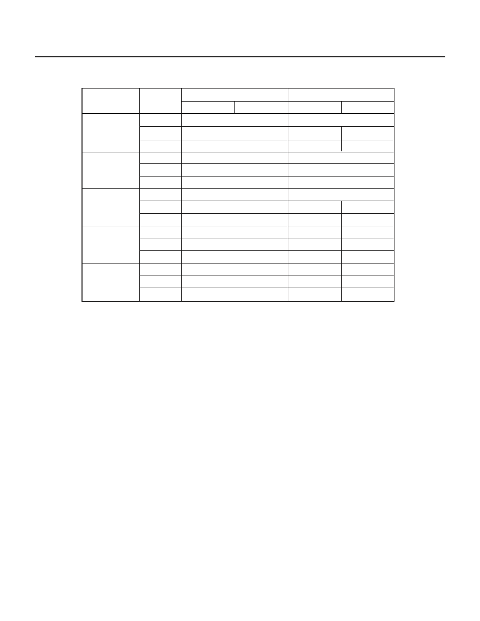
Table 6-1 Port 0 Operating Modes and Operations Needed for the Port 0 Buffer Registers
8-bit port mode
8-bit real-time
output port
mode
4-bit separate
real-time output
port mode
P00-P03: Port
P04-P07: Real-time
output port mode
P00-P03: Real-time
output port mode
P04-P07: Port
High-order 4 bits
Read operation
Write operation
Operating mode
P0
P0L
P0H
P0
P0L
P0H
P0
P0L
P0H
P0
P0L
P0H
P0
P0L
P0H
Register
Low-order 4 bits
High-order 4 bits
Low-order 4 bits
Output latch
Buffer register
Note
Buffer register
Note
Output latch
Buffer register
Note
Buffer register
Note
Output latch
Buffer register
Note
Buffer register
Note
Output latch
Buffer register
Note
Buffer register
Note
Output latch
Buffer register
Note
Buffer register
Note
Output latch
—
Buffer register
Buffer register
—
—
Buffer register
Buffer register
—
—
Buffer register
Buffer register
—
—
Output latch
—
Buffer register
Buffer register
—
Output latch
—
—
Buffer register
Buffer register
—
Note The contents of the P0H are read to the high-order 4 bits, and the contents of the P0L are read to the low-order 4 bits.
Remark —: The output latches or buffer registers are not affected.
Example of setting data in the buffer registers
• 4-bit
× 2-channel operation
MOV P0L, #05H
; Sets 0101B in the P0L register
MOV P0H, #0C0H
; Sets 1100B in the P0H register
• 8-bit
× 1-channel operation
MOV P0L, #0C5H
; Sets 0101B in the P0L register
and 1100B in the P0H register
Or,
MOV P0H, #0C5H
The following three sources can determine the timing at which data is output to an output latch.
• Interrupt from 8-bit timer/counter 1 (INTC10 or INTC11)
• INTP0 external interrupt