Chapter 7 timer/counter units – NEC PD78214 User Manual
Page 226
197
Chapter 7 Timer/Counter Units
7
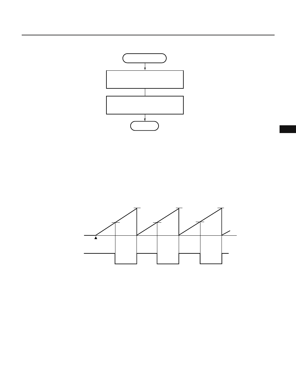
Fig. 7-106 Interrupt Request Handling for Pulse Width Calculation
(4) PWM output operation
In PWM output operation, a pulse signal with a duty factor determined by the value set in a compare register
is output. (See Fig. 7-107.)
The duty factor of a PWM output signal can be changed in steps of 1/256 from 1/256 to 255/256.
In addition, 8-bit timer 2 (TM2) has two compare registers, so that two types of PWM signals can be output.
Fig. 7-108 shows the setting of control registers. Fig. 7-109 shows the setting procedure. Fig. 7-110 shows
the procedure for changing the duty factor of PWM output.
Fig. 7-107 Example of PWM Signal Output by 8-Bit Timer/Counter 2
FFH
FFH
FFH
Timer starts
0H
TM2
count value
(active high)
TO3
INTP1 interrupt
Store captured value in memory
Calculation of pulse width
Yn=X
n+1
– Xn
RETI
X
n+1
←CR22