Chapter 7 timer/counter units – NEC PD78214 User Manual
Page 222
193
Chapter 7 Timer/Counter Units
7
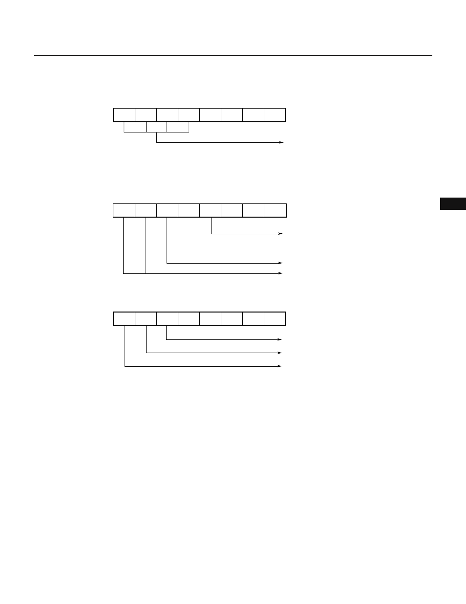
Fig. 7-101 Setting of Control Registers for Interval Timer Operation (2)
(a) Prescaler mode register 1 (PRM1)
(b) Capture/compare control register 2 (CRC2)
(c) Timer control register 1 (TMC1)
7
6
5
4
3
2
1
0
PRS23
×
0
PRM1
Specifies count clock
(x/f
CLK
; where x = 16, 32, 64,
128, 256, 512,
or external clock)
PRS22 PRS21 PRS20
Ч
Ч
7
6
5
4
3
2
1
0
1
0
0
0
Ч
0
0
TMC1
×
Normal mode
Overflow flag
Enables counting
7
6
5
4
3
2
1
0
0
1
CRC2
Enables clearing TM2, when CR21 coincides
with TM2
0
0
1
0
0
0
Disables clearing TM2, when TM2 captured
Both TO2 and TO3 are used for toggle output