Chapter 7 timer/counter units – NEC PD78214 User Manual
Page 230
201
Chapter 7 Timer/Counter Units
7
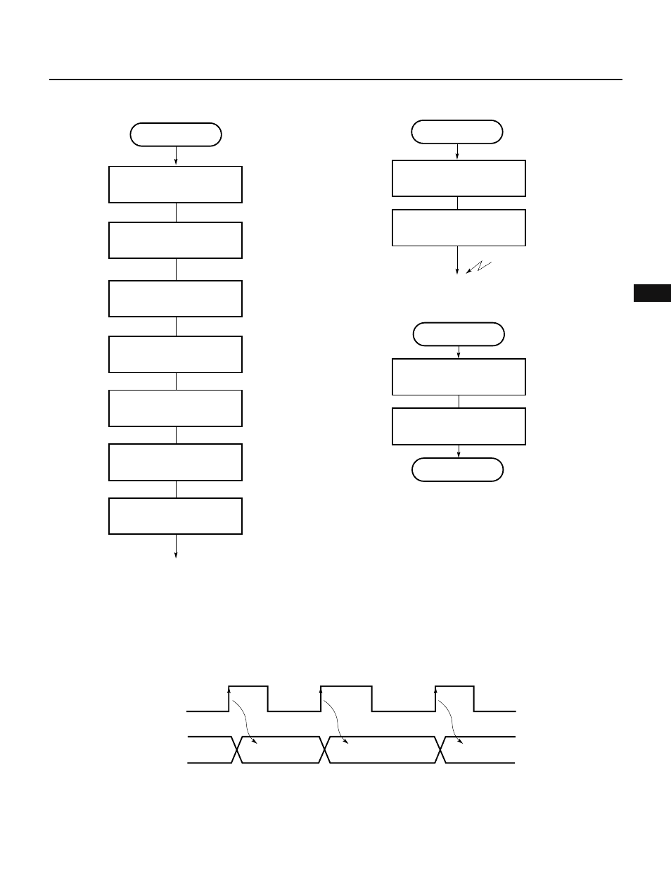
Fig. 7-113 Setting Procedure for PPG Output
Fig. 7-114 Changing Duty Factor of PPG Output
(6) External event counter operation
When functioning as an external event counter, 8-bit timer/counter 2 counts clock pulses externally applied
to the CI pin.
As shown in Fig. 7-115, the value of 8-bit timer 2 (TM2) is incremented on each valid edge specified (rising edge
only in this case) of a pulse signal applied to the CI pin.
Fig. 7-115 External Event Counter Operation (When Only One Edge Is Used)
n
n + 1
n + 2
TM2
CI pin input
Fig. 7-116 shows the setting of control registers, and Fig. 7-117 shows the setting procedure when 8-bit timer/
counter 2 functions as an external event counter.
Remark The value of TM2 is less then the number of input clock pulses by 1.
PPG output
Set CRC2 register
Set TOC register
Set P34 pin in control mode
Set period in compare
register CR21
Set count clock in PRM1
CRC2
←D8H
PMC3.6
←1
Set duty factor in compare
register CR21
Start counting
; Sets bit 7 of TMC1
CE2
←1
CIF20
←0
Preprocessing for
changing duty factor
Clear INTC20 interrupt request
flag
; Clears bit 3 of IF0H
Enable INTC20 interrupt
; Clears bit 3 of MK0H
INTC20 interrupt
Duty factor changing
processing
Set duty factor in CR20
CMK20
←0
Disable INTC20 interrupt
; Sets bit 3 of MK0H
CMK20
←1
RETI