3 asynchronous serial interface operations, 1 data format, 2 parity types and operations – NEC PD78214 User Manual
Page 276: Chapter 9 asynchronous serial interface
247
Chapter 9 Asynchronous Serial Interface
9
Fig. 9-3 Format of the Asynchronous Serial Interface Status Register (ASIS)
Caution Be sure to read the reception buffer (RXB) contents, even if a reception error occurs. Otherwise, an overrun error will occur when
the next data is received, and the error status will persist.
9.3 ASYNCHRONOUS SERIAL INTERFACE OPERATIONS
9.3.1 Data Format
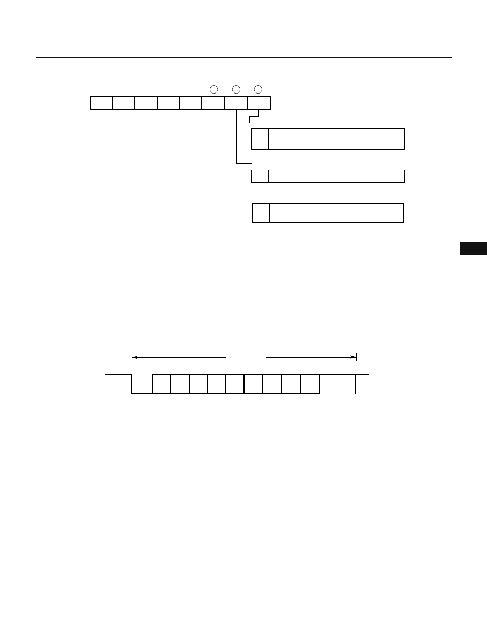
Fig. 9-4 shows the format of the transmit/receive data. One data frame consists of a start bit, character bits, a parity
bit, and one or two stop bits.
The asynchronous serial interface mode register (ASIM) specifies the number of character and stop bits, and
whether to use a parity bit.
Fig. 9-4 Format of the Transmission/Reception Data at the Asynchronous Serial Interface
• Start bit : 1 bit
• Character bits : 7 or 8 bits
• Parity bit : Even parity, odd parity, 0 parity, or no parity
• Stop bit : 1 or 2 bits
The serial transmission rate can range from 1.43 bps to 93.75 kbps according to the setting of the asynchronous
serial interface mode register and baud rate generator or timer/counter 3.
If an error occurs during reception of serial data, the error can be identified by reading the contents of the
asynchronous serial interface status register (ASIS).
9.3.2 Parity Types and Operations
The parity bit is used to detect a bit error in transmit/receive data. Usually, the same parity bit is used at both the
transmission and reception ends. When even or odd parity is used, a 1-bit (the odd number of bits) error can be
detected. When 0 parity or no parity is used, no error can be detected.
• Even parity
When the transmit data has an odd (or even) number of 1 bits, the parity bit is set to 1 (or 0), so that the number
of 1 bits in the data becomes even. When data is received, the number of 1 bits in it is counted, and if the number
of 1 bits is odd, a parity error is detected.
ASIS
7
6
5
4
3
2
1
0
0
0
0
0
0
PE
FE
OVE
Overrun error flag
Parity error flag
1
1
1
Indicates that the next reception is completed
before data is read from receive buffer
Framing error flag
Indicates that specified parity for transmit
data does not match receive data parity
Indicates that stop bit is not detected
D0
D1
D2
D3
D4
D5
D6
D7
Parity
bit
Start
bit
Stop bit
1 data frame