Chapter 7 timer/counter units – NEC PD78214 User Manual
Page 178
149
Chapter 7 Timer/Counter Units
7
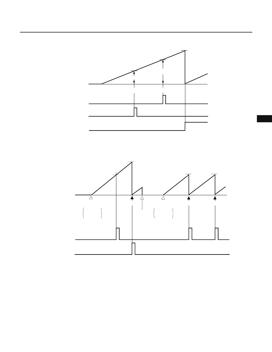
Fig. 7-51 Compare Operation
Remark CLR10 = 0, CLR11 = 0, CM = 0
Caution When using an in-circuit emulator, see the notes described in Section 7.5.4.
Fig. 7-52 TM1 Cleared After a Coincidence Is Detected
(2) Capture operation
Eight-bit timer/counter 1 performs a capture operation to load the count value of the timer into the capture
register in synchronism with an external trigger.
As an external trigger, a valid edge detected on the external interrupt request (INTP0) input pin is used (capture
trigger). In synchronism with a capture trigger, the count value of 8-bit timer 1 (TM1) in count operation is
loaded and held in the capture/compare register (CR11) specified to perform capture operation. Until the next
capture trigger occurs, the value of the CR11 register is held.
A valid edge used as a capture trigger is set using external interrupt mode register 0 (INTM0). When both a
rising edge and falling edge are set as capture triggers, the pulse width of an applied external signal can be
measured. When a capture trigger is generated using one edge, the period of an input pulse signal can be
measured.
For the detailed format of the INTM0 register, see Fig. 11-1 in Chapter 11.
Caution When using an in-circuit emulator, see the notes described in Section 7.5.4.
Coincidence
Count starts
0H
CE1
←1
Coincidence
Value of CR11
Value of CR10
FFH
TM1
count value
INTC10
interrupt request
INTC11
interrupt request
OVF1
CE1
←0
CE1
←1
CLR10
←0
CLR11
←1
CE1
←0
CLR10
←1
CLR11
←0
CR10
CR11
CR10
CR10
TM1
count value
Count starts
Cleared
Cleared
Cleared
Count starts
Count stops
0H
INTC10
interrupt request
INTC11
interrupt request