NEC PD78214 User Manual
Page 451
422
µ
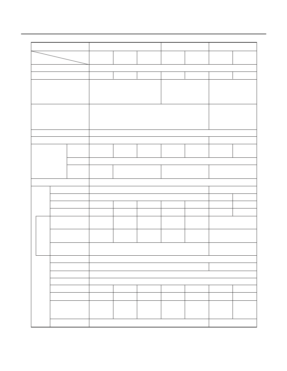
PD78214 Sub-Series
Series name
µPD78214 Sub-Series
µPD78218A Sub-Series
µPD78224 Sub-Series
µPD78214
(
µPD78P214)
Number of basic instructions
Minimum instruction execution time
µPD78213
µPD78212
µPD78224
(
µPD78P224)
µPD78220
µPD78218A
(
µPD78P218A)
µPD78217A
Product name
Item
333 ns
500 ns
333 ns
333 ns
500 ns
333 ns
500 ns
65 (instructions common to all 78K/II series products)
When the stack area is configured in
the internal dual-port RAM: 5 or 7
Other cases: 7 or 9
PUSH PSW instruction
execution time (number of
clocks)
When the stack area is
configured in the internal
dual-port RAM: 6
Other cases: 8
–40 to +85˚C,
V
DD
= +5 V
±5%
–10 to +70˚C,
V
DD
= +5 V
±10%
8 bits
Ч 8 Ч 4 banks
General-purpose registers
Bank registers
ROM
(bytes)
None
EEPROM
RAM
(bytes)
8K
None
16K
16K
None
None
512
640
Memory space
Program memory space: 64K bytes, Data memory space: 1M byte
I/O pins
Input
Output
I/O
Total
With a pull-up
resistor
LED direct drive
output
Transister direct
drive output
P0
P1
P2
P3
P4
P5
P6
P7
P6 and PM6
P6 only
14
8
12
12
20
28
10
28
35
25
10
28
54
36
54
63
45
36
54
34
16
34
None
16
34
8
None
16
0
16
8
0
16
8-bit output port
—
8-bit I/O port
8-bit input port
8-bit I/O port
8-bit I/O port
8-bit I/O port
—
8-bit I/O port
—
8-bit I/O port
—
8-bit I/O port
8-bit output port
—
8-bit I/O port
—
8-bit I/O port
—
4-bit output port
+
4-bit I/O port
4-bit output port
+
4-bit I/O port
4-bit output port
+
2-bit I/O port
4-bit output port
+
4-bit I/O port
4-bit output port
+
2-bit I/O port
4-bit output port
+
4-bit I/O port
6-bit input port
7-bit I/O port
4-bit output port
+
2-bit I/O port
Operating temperature and
voltage ranges
Other than
µPD78P2148A : –40 to +85˚C, V
DD
= +5 V
±10%
µPD78P2148A
: –40 to +85˚C, V
DD
= +5 V
±0.3 V
32K
384
1024
When the stack area is
configured in the internal
dual-port RAM: 5 or 7
Other cases: 7 or 9
Ancillary function
pins
Note
Internal memory
Note The ancillary function pins are included in the I/O pins.