Chapter 7 timer/counter units – NEC PD78214 User Manual
Page 228
199
Chapter 7 Timer/Counter Units
7
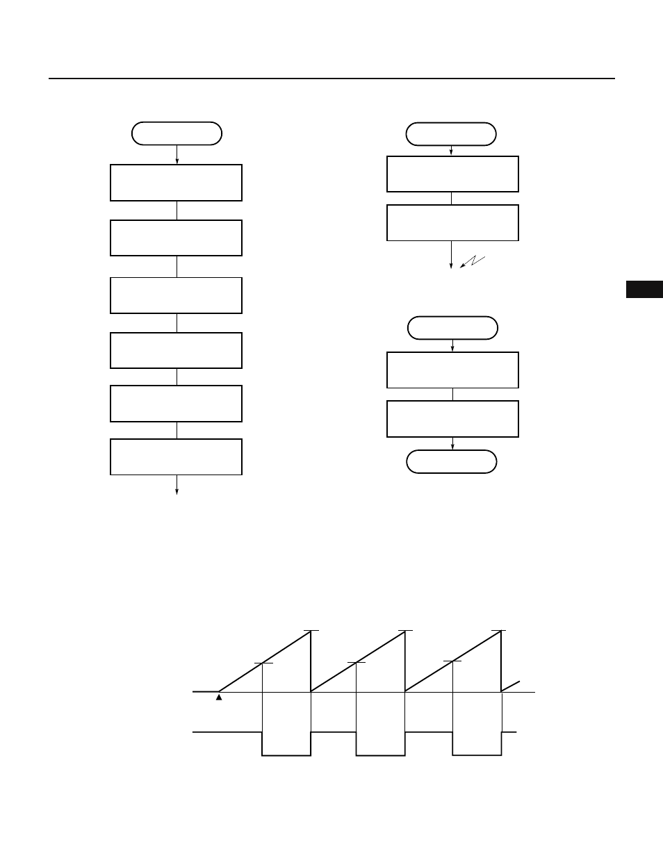
Fig. 7-109 Setting Procedure for PWM Output
Fig. 7-110 Changing Duty Factor of PWM Output
(5) PPG output operation
In PPG output operation, a pulse signal with a period and duty factor determined by the values set in the
compare registers is output. (See Fig. 7-111.)
Fig. 7-112 shows the setting of control registers. Fig. 7-113 shows the setting procedure. Fig. 7-114 shows
the procedure for changing the duty factor of PPG output.
Fig. 7-111 Example of PPG Signal Output by 8-Bit Timer/Counter 2
Timer starts
0H
TM2
count value
(active high)
TO2
CR20
CR20
CR20
CR21
CR21
CR21
PWM output
Set CRC2 register
Set TOC register
Set P34 pin in control mode
Set initial value in compare
register
Set count clock in PRM1
CRC2
←90H
PMC3.4
←1
Start counting
; Sets bit 7 of TMC1
CE2
←1
CIF21
←0
Preprocessing for
changing duty factor
Clear INTC21 interrupt request
flag
; Clears bit 0 of IF0H
Enable INTC21 interrupt
; Clears bit 0 of MK0H
INTC21 interrupt
Duty factor changing
processing
Set duty factor in CR21
CMK21
←0
Disable INTC21 interrupt
; Sets bit 0 of MK0H
CMK21
←1
RETI