7 macro service type c, Chapter 12 interrupt functions – NEC PD78214 User Manual
Page 360
331
Chapter 12 Interrupt Functions
12
12.4.7 Macro Service Type C
(1) Operation
The type C macro service controls 8-bit timer/counter 1 and the real-time output port simultaneously. This
macro service transfers data to both the compare register for 8-bit timer/counter 1 and the buffer register for
the real-time output port upon one interrupt request.
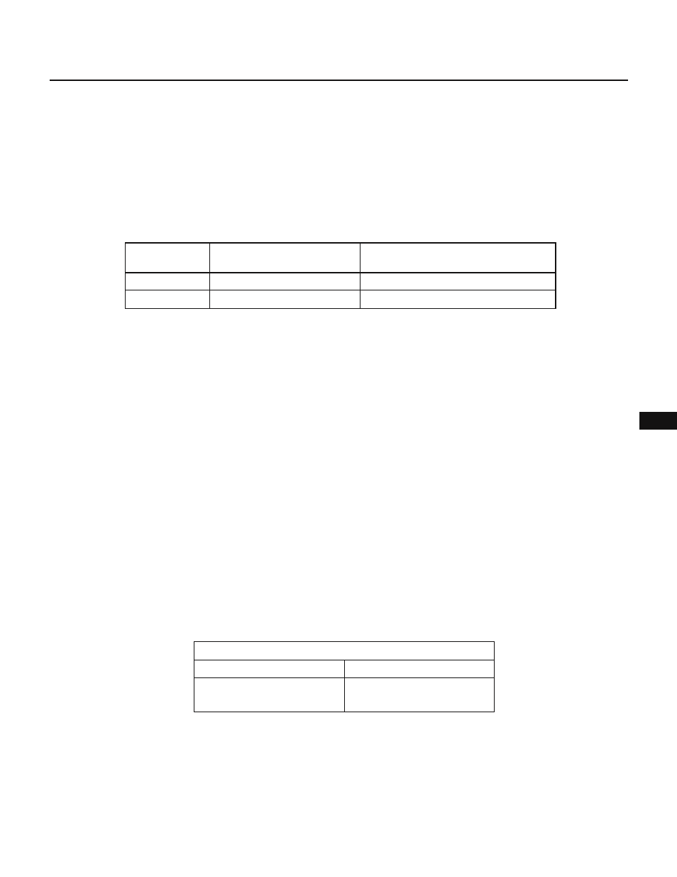
Only INTC10 and INTC11 can use the type C macro service. Their transfer destination registers are
predetermined as listed in Table 12-8.
Table 12-10 Interrupt Requests That Can Specify Macro Service and SFRs (Type C)
CR10
CR11
INTC10
INTC11
P0L or P0H (specified by the mode register)
P0L or P0H (specified by the mode register)
Data transfer destination
addressed by the MPT
Data transfer destination
addressed by the MPD
Besides the basic data transfer function described above, the type C macro service can have the following
ancillary functions to reduce the required buffer area and load on the software.
(a) Retention of the timer macro service pointer
It can be specified whether to retain or increment the timer macro service pointer (MPT).
(b) Automatic addition
This function adds data addressed by the timer macro service pointer (MPT) to the value in the compare
register, and transfers the sum to the compare register.
If this function is not used, data addressed by the MPT is transferred to the compare register.
(c) Ring control
This function repeats to output a pattern of data with a predetermined length automatically.
These ancillary functions are specified in the mode register in the macro service control word.
Cautions
1. With the type C macro service, the MPT and MPD are incremented only at the lower 8 bits. If a carry occurs at bit 7 of
the MPTL or MPDL, it is ignored; so the higher 8 bits are not affected.
2. When the external memory is expanded (or always with the
µPD78213), an illegal write access operation may occur during
the type C macro service. This illegal write access occurs when the following condition is satisfied.
• When the MPTL address is 0FED0H through 0FEDFH.
An illegal write access is performed in the same manner as the normal memory access. In addition, wait states may be
inserted according to the setting of the PW20 and PW21 bits of the memory expansion mode register (MM). Table 12-
11 lists the conditions under which an illegal write access occurs and the corresponding operations.
Table 12-11 Illegal Write Access Conditions and Corresponding Operations
Address
Address of a destination SFR
(CR10 or CR11)
Illegal write access
Data
Lower 8 bits of the address of
the MPTL
This problem may be solved by the following method.
• Locate the MPTL so that its address does not coincide with an address from 0FED0H through 0FEDFH.
The above problem also occurs with an in-circuit emulator.
Interrupt request