NEC PD78214 User Manual
Page 315
286
µ
PD78214 Sub-Series
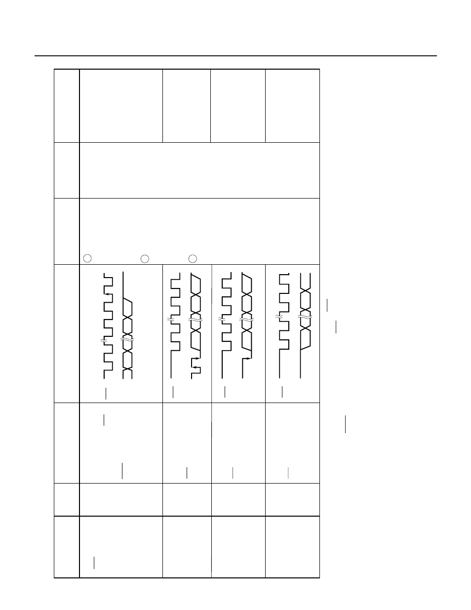
Table 10-2 Signals in SBI Mode (3/3)
Notes
1.
If WUP is set to 0, CSIIF is always set at the rising edge of the eighth pulse of the SCK clock.
If WUP is set to 1, CSIIF is set at the rising edge of the eighth pulse of the SCK clock only when an address is received.
2.
Data is neither sent nor received in the BUSY state. Data transfer is started once the READY state has been established.
Synchronization clock
for output address,
command, or data, ACK
signal, and synchronous
BUSY signal.
The address, command,
or data is transferred
during the first eight cycles.
8-bit data transferred in
synchronization with
SCK after the REL and
CMD signals are output
8-bit data transferred in
synchronization with
SCK after the CMD
signal is output without
the REL signal
8-bit data transferred in
synchronization with
SCK when neither the
REL signal nor CMD
signal is output
Serial clock
(SCK)
Address
(A7 to A0)
Command
(C7 to C0)
Data
(D7 to D0)
Output
device
Definition
Output condition
CSIIF is set (at
the rising edge
of the eighth
clock pulse).
Note 1
Influence on flag
Description
T
iming of signal
output to the serial
data bus
Address of a slave
device on the serial
bus
Instruction and
message to a slave
device
Data to be processed
by the slave or
master device
Signal name
T
iming chart
Master
Master
Master
Master/
slave
SCK
SB0
12
7
8
9
1
0
SCK
SB0
12
7
8
SCK
SB0
12
7
8
CMD
REL
CMD
SCK
SB0
12
7
8
When CTXE is set
to 1, the instruction
to write data into
the SIO is
executed (a serial
transfer start is
specified).
Note 2
When CTXE is set
to 0 and CRXE is
set to 1, the
instruction to read
data from the SIO
is executed.
The CRXE bit is
changed from 0
to 1.
1
2
3