4 notes – NEC PD78214 User Manual
Page 327
298
µ
PD78214 Sub-Series
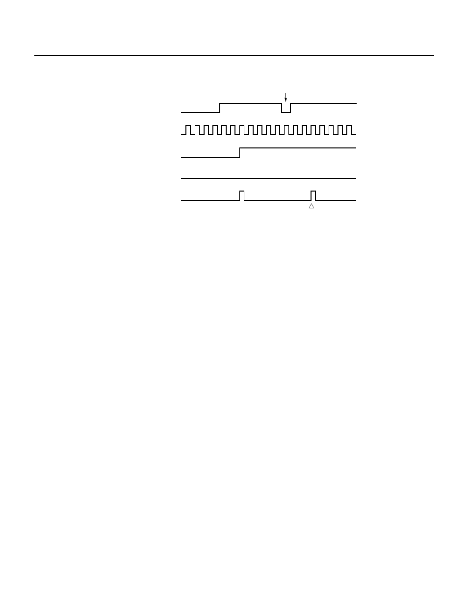
(b) Erroneously detected edge during input of a high signal
INTPn input (n = 0 to 6)
Erroneously detected edge
f
CLK
/4
After noise rejection
Falling edge detection
Rising edge detection
Noise
"L"
If the IE-78210-R is used, the real-time output port, timer/counter, and A/D converter operate according to the
erroneously detected edge. If another in-circuit emulator is used, these components operate as described below:
• Real-time output port : Operates according to the erroneously detected edge.
• A/D converter
: Operates according to the erroneously detected edge.
• Capture or clear operation of the timer/counter :
Carried out independently of the erroneously detected
edge. Even if the erroneously detected edge causes an
interrupt, the capture value is not updated. The value of
CR22 becomes undefined after being read by the CPU.
• Compare operation of the timer/counter : If a mode for performing a clear operation after a capture operation
is selected, or if timer/counter 2 is used as an external event
counter, the erroneously detected edge causes the timing of
match interrupt generation to be changed. As a result, the timing
of match interrupt generation will disagree with that when the
values of the timer/counter and compare register match. If the
mode for performing a clear operation after a capture operation is
selected, the timing of match interrupt generation can be cor-
rected by inputting a correct edge or by stopping the timer/
counter. If timer/counter 2 is used as an external event counter,
the timing of the match interrupt generation can be corrected by
stopping the timer/counter. Timer output is not affected by the
erroneously detected edge and operates according to the correct
timing.
11.4 NOTES
(1) If an edge is input while a valid edge is changed, it cannot be determined whether the new edge is judged as
being a valid edge.
(2) Noise elimination by analog delay is carried out on pin P20. An edge is detected up to 10
µs after the edge
is actually input. Pin P20 differs from pins P21 to P26 in that the delay time depends on the characteristics of
the device.
(3) On pins P21 to P26, digital noise elimination is carried out with the f
CLK
/4 clock. It takes about 8 to 12 cycles
of the f
CLK
clock to detect an edge after it is actually input.
(4) If the width of a pulse input to pins P21 to P26 corresponds to 8 to 12 cycles of the f
CLK
clock, it cannot be
determined whether the pulse is detected as being a valid edge. To ensure the accurate detection of a pulse,
hold the pulse at an identical level for 12 clock cycles or longer.